
Outdoor
Alerting
System
System Installation, Operation
and
Maintenance
Manual

Copyright
Copyright 2019, by Earth Networks, Inc.
All Rights Reserved.
Manual Copyright, 2019, by Earth Networks, Inc.
All Rights Reserved.
Information in this document is subject to change without notice and does not represent a commitment on the
part of Earth Networks, Inc.
FCC Compliance
This equipment has been tested and found to comply with the limits for a Class B digital device, pursuant to part 15
of the FCC Rules. These limits are designed to provide reasonable protection against harmful interference in a
residential installation. This equipment generates, uses and can radiate radio frequency energy and, if not installed
and used in accordance with the instructions, may cause harmful interference to radio communications. However,
there is no guarantee that interference will not occur in a particular installation. If this equipment does cause harmful
interference to radio or television reception, which can be determined by turning the equipment off and on, the user is
encouraged to try to correct the interference by one or more of the following measures:
—Reorient or relocate the receiving antenna.
—Increase the separation between the equipment and receiver.
—Connect the equipment into an outlet on a circuit different from that to which the receiver is connected.
—Consult the dealer or an experienced radio/TV technician for help.
Disclaimer
The procedures, methods, and hardware described in this manual are intended to provide general guidelines and
instructions for installing the Earth Networks Outdoor Alerting System. Each installation site is unique and
each site may require special considerations that are beyond the scope of this manual. Any questions not
covered within this manual should be directed to Earth Networks Technical Support at (800) 624-4205 or email
All procedures, methods, and hardware used to install an Earth Networks Outdoor Alerting System must
conform to all applicable building codes (national, state, and local). Installation subcontractors are responsible
for complying with all applicable codes. Buyer and/or installer provided hardware must be equivalent or better
(according to industry standards) than that specified in the Earth Networks Installation Manual.
The buyer/installer is responsible for any damage caused by installation of the Earth Networks Outdoor Alerting
System.
THINK SAFETY FIRST!
Warranty. The Seller warrants the hardware purchased by the Buyer against defects in
workmanship and materials for a period of one (1) year from date of delivery under this
contract. The Seller shall, at its sole option, either repair or replace defective items. Buyer
is responsible to return of defective items to Seller by means specified by the Seller. The
Buyer shall bear all shipping expenses. Packing of defective items for return is
responsibility of Buyer. Damage due to natural causes (storms, lightning, flying debris, etc.)
is not covered by this warranty. Damage resulting from Buyer negligence or mishandling of
hardware and software is not covered by this warranty.

Table of Contents
Copyright .................................................................................................................................... 3
FCC Compliance ........................................................................................................................ 3
Disclaimer .................................................................................................................................. 3
Thank You! ................................................................................................................................. 8
Introduction ................................................................................................................................ 8
Plan Ahead! ................................................................................................................................ 9
Safety! ........................................................................................................................................ 9
Installation ................................................................................................................................ 10
Site Evaluation ...................................................................................................................... 10
Determining Horn Locations .................................................................................................. 10
Determine a Suitable Informer Location ................................................................................ 10
Getting Started ...................................................................................................................... 11
Outdoor Components ............................................................................................................ 11
Indoor Components ............................................................................................................... 10
Tools Required...................................................................................................................... 10
Additional Tools/ Materials Needed ....................................................................................... 11
Site Preparation .................................................................................................................... 11
Installing Outdoor Equipment .................................................................................................... 13
Assembling the Horn(s) ......................................................................................................... 13
Outdoor System Wiring ......................................................................................................... 16
Power Connections (all horns) ........................................................................................... 16
Horn Connections.............................................................................................................. 16
Strobe Connections ........................................................................................................... 17
Data Connections (base horn only) ................................................................................... 17
Installing Informer ..................................................................................................................... 18
Informer Wiring ..................................................................................................................... 18
Data Cable Connections ....................................................................................................... 18
Additional Informer Connections ........................................................................................... 19
Configuration ............................................................................................................................ 19
Overview ............................................................................................................................... 19
Configuration via Web Browser Interface ............................................................................... 19
Computer Configuration ........................................................................................................ 19
Login .................................................................................................................................... 20
System Server and Unit ID Assignment ................................................................................ 20
Change Config User Password ............................................................................................. 21
Static IP Address, Site ID, and Location Assignment ............................................................ 23
Backup Configuration ............................................................................................................ 26
Informer Operating Instructions ................................................................................................ 27

General Information .............................................................................................................. 27
LED Indicators ...................................................................................................................... 27
Keypad ................................................................................................................................. 29
Testing and Training ................................................................................................................. 29
Troubleshooting ........................................................................................................................ 27
Maintenance ............................................................................................................................. 28
Additional Information ............................................................................................................... 28
Specifications ........................................................................................................................... 29
Informer Specifications .......................................................................................................... 29
Horn Specifications ............................................................................................................... 29
Wiring Diagram ......................................................................................................................... 30

Thank You!
Thank you and congratulations on acquiring the Earth Networks Outdoor Alerting System. The Earth
Networks
Outdoor Alerting System provides additional lightning safety on your property through an audible
warning when lightning is detected within predefined parameters.
By installing and operating the entire Earth Networks system, you become an essential part of the Earth
Networks program, an integrated network of weather stations comprising the largest weather monitoring
system in the world.
Introduction
The Earth Networks Outdoor Alerting System is the most advanced localized automated weather
warning system available. The system minimizes nuisance alerts and provides real-time warnings based on
current environmental conditions in the area.
The alert system is comprised of an indoor alert device, the Informer, and one or more outdoor notification
horns (with strobe light). The Informer connects to the earth Networks alert system server via the internet
to receive lightning alert notices. The Informer activates a base outdoor horn via a wired connection. Where
additional horns have been purchased a wireless radio transmission is sent, activating them.
The indoor Informer contains a loud internal speaker with an adjustable volume level to alert personnel
indoors.

Plan Ahead!
Read this entire manual before beginning installation. The Earth Networks Outdoor Alerting System
installation can be straightforward and easy to complete if all steps are followed closely.
The most important aspect of preparation is safety. Installation of the Earth Networks Outdoor Alerting
System requires working with electrical cable, drilling through walls or other dense support structures,
standing on ladders, and possibly, walking on roofs. Please carefully read the following section on
“Safety.”
Please also pay close attention to the section on “Site Evaluation.” A complete site evaluation determines
proper placement of the Outdoor Alerting System and will prevent the need to have to re-locate the system
due to inadequate coverage.
All additional parts needed (such as ladders, drills, bits, etc.) should be assembled and inspected before
beginning installation. Earth Networks cannot accept responsibility for damage caused by these tools
so all safety precautions should be strictly adhered to, including the use of leather gloves and goggles
when appropriate.
For questions, call Earth Networks Technical Support at (800) 624-4205 or email
Safety!
Only qualified personnel should install the Outdoor Alerting System.
While installation of the Outdoor Alerting System is not particularly difficult, it does usually require
installation near the rooftop and working with electrical wiring, which presents some amount of risk.
To limit risk to self and property, this manual should be thoroughly read and understood before
beginning installation. Adhere to all warnings on the unit and in the operating instructions.
Installation must conform to national, state, and local building code requirements with the most
stringent guidelines being adhered to.
The Outdoor Alerting System should only be installed by someone comfortable with being on a high
ladder or rooftop and who is authorized by the site to perform the installation. Roof and ladder safety is
crucial!

Allow only qualified Electricians to make electrical connections. Take all reasonable safety precautions –
double checking a power cable connection could save a life.
Stay as far away from other electrical wiring as possible. Never allow the mast, cabling, a drill bit, or
any other item to contact electrical wires or conduit. Injury or death could result.
A qualified installer will need to securely mount the outdoor unit to a supporting structure capable of
sustaining the weight of the unit (approximately 50 pounds) by using appropriate tools and hardware.
Failure to properly secure the Outdoor Alerting Horn could result in the unit separating from the support
structure and falling. This would not only damage the system, but could injure anyone standing nearby.
Installation
Site Evaluation
Placement of the individual warning system horns is critical for full area coverage. The following
guidelines should assist with choosing the proper placement sites.
Determining Horn Locations
The following guidelines should be used when determining to position the horn(s):
•
Horns have a 500 yard radius of coverage (line of sight).
•
Location(s) must have access to power within 20 ft.
•
Horn(s) must be at least 8 ft. off the ground and clear of obstructions (Trees, Roofline, etc.).
•
The horn location(s) must have a significant structure to mount the horns to that can handle the load (new or
existing).
Determine a Suitable Informer Location
When picking a location for the Informer first consider the following criteria:
•
Place the Informer away from electrically noisy devices to avoid interference.
•
A wired Ethernet connection is required for the Informer. Ethernet wire runs must be within 300’ from
the nearest network switch.
•
Place the Informer in an area where the alert can be clearly heard by necessary personnel.
•
Do not place the Informer near water.
•
The Informer needs to be located within six feet of an AC power receptacle.
Getting Started
Carefully unpack, set out, and identify each part and inspect for damage. If any damage is noticed, please
call Earth Networks Technical Support at (800) 624-4205 or email support@earthnetworks.com
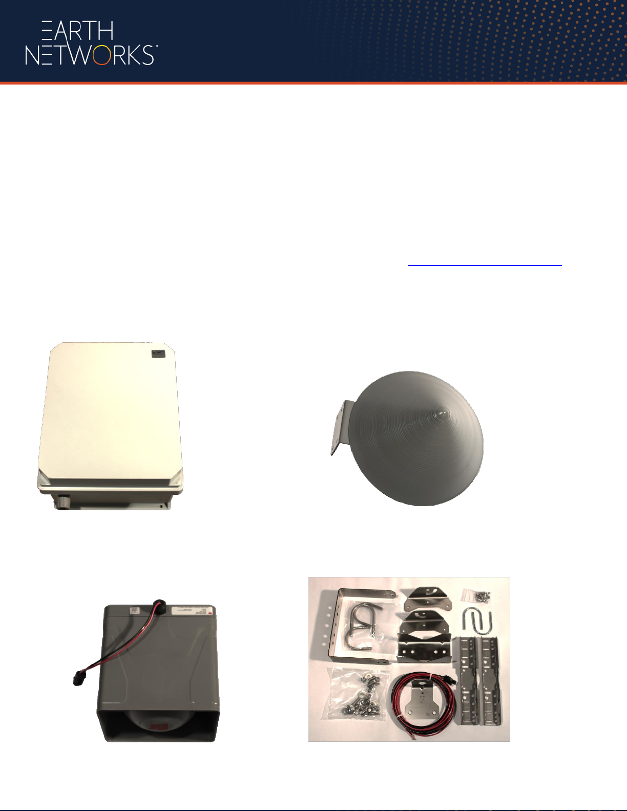
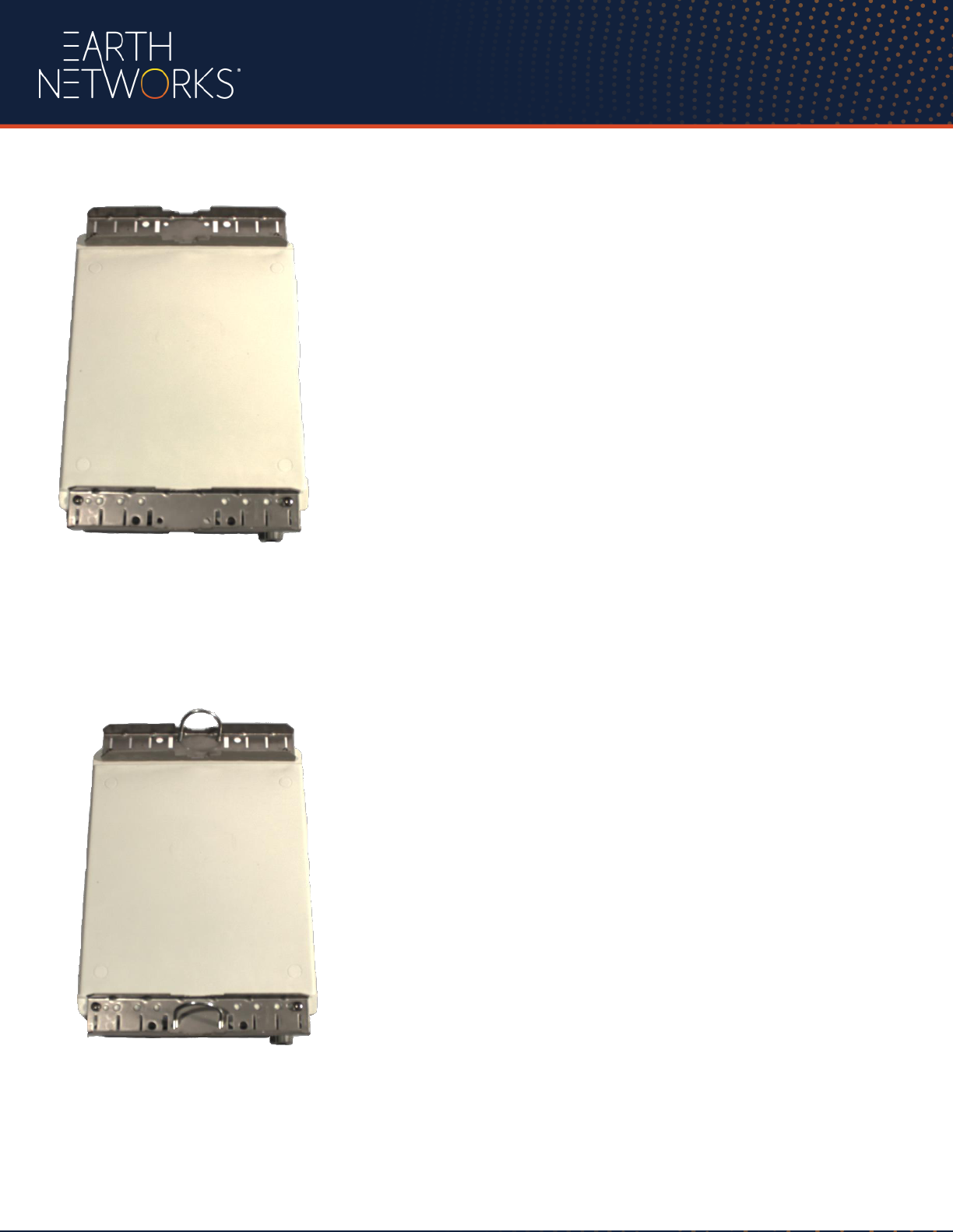
Outdoor Components
Outdoor Control Box Sound Dispersion Cone
Outdoor Horn Mounting Hardware

Indoor Components
Informer and power supply
Tools Required (minimum)
1 Philips #2 Screwdriver
1 Philips #2 Short Screwdriver “Stubby”
1 Slotted Screwdriver (2mm blade)
2 9/16” Box Wrenches
1 7/16” Box Wrench
1 3/8” Nut Driver or equivalent wrench
1 Pair of Pliers
1 Pair Wire Stripper/Cutters
Cable Ties

Additional Tools/ Materials Needed (Not supplied by Earth Networks)
•
Heavy-duty drill with bits sized up to 1-1/4” – bits must be appropriate for material being drilled into
(masonry, wood, metal, etc.) and must be long enough to penetrate the support walling from exterior
to interior (possibly as much as 10” or more).
•
Fish Tape to pull cable through wall
•
Electrical Tape to tape the ends of cables for protection and to hold connectors and cables together.
•
An adjustable ladder
•
Metal saw for cutting mast if necessary
•
10 ft x 1.5 in. inside diameter (ID) galvanized rigid conduit (GRC). 1 piece or more for each horn,
depending on the mounting height (available at most home improvement stores).
•
Mounting platform for each horn (non-penetrating roof mount, tripod mount etc…)
•
Additional mounting hardware as needed
•
Silicone
•
Data cable (for connection from base unit to informer)
•
Cat 5 LAN cable (for connecting Informer to network)
•
18 awg wire for the Strobe
Site Preparation
The install site needs to have the following in place to ensure a successful installation:
•
Power available for all components
•
Internet access for all components with the following outbound connections allowed: port 80
•
Access to a licensed electrician during install for hardwiring power to the horn(s)
Installing Outdoor Equipment
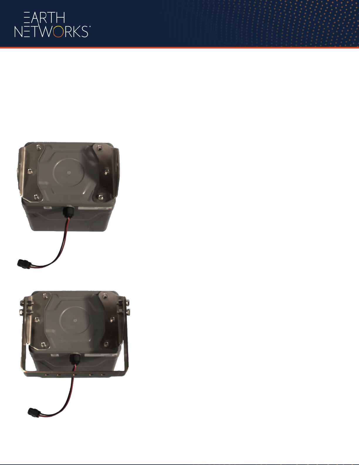
Assembling the Horn(s)
1. Connect the left and right mounting
brackets to the bottom of the E-Horn using
the provided screws.
2. Attach the square pole bracket to the left
and right mount brackets using the lock
washers, flat washers, nuts and screws
provided.
3. Place the pole clamp and strobe bracket
on to the square pole bracket using the
longer U-Bolt provided along with the lock
washers and nuts.
**NOTE: Two of the U-Bolts are shorter
and are to be used with the dispersion cone.
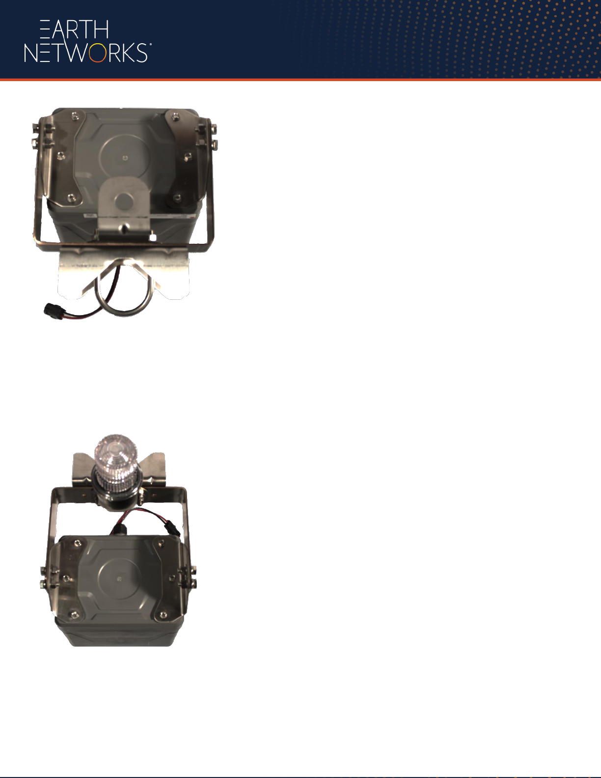
4. Next attach the strobe onto the strobe
mounting bracket and secure it with the
strobe nut.
**NOTE: Please make sure to attach the
wire be used for install prior to doing this.
5. Locate the mounting brackets for the
Outdoor control box. Attach the mounting
brackets in the orientation shown using the
provided screws and nuts.
6. Next take the two U-Bolts and attach
them to the brackets as shown using the nuts
provided.
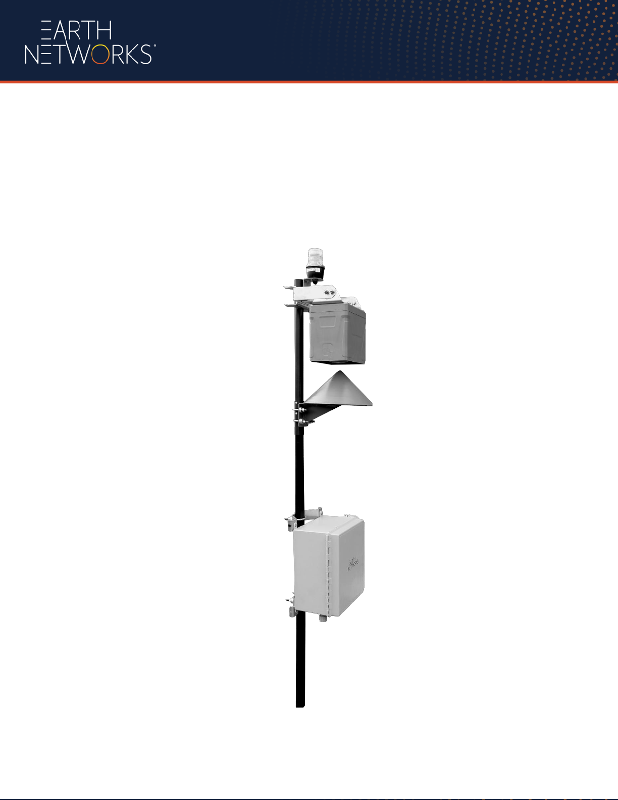
7. Now the components can be mounted to the mast
a. The assembled Horn with Strobe should be mounted to the top of the mast.
b. The Sound Dispersion Cone should be mounted so that the point is 2” below the Horn.
c. The assembled OAS Control Box should be mounted lower on the pole.
8. Attach the assembled horn and mast to the pre-determined existing (solid) structure.
Fully Assembled OAS (Repeat this procedure for each additional horn purchased)
Outdoor System Wiring
All Outdoor Alerting System site locations need to be hardwired for 120/240 VAC with at least a 15
amp circuit.
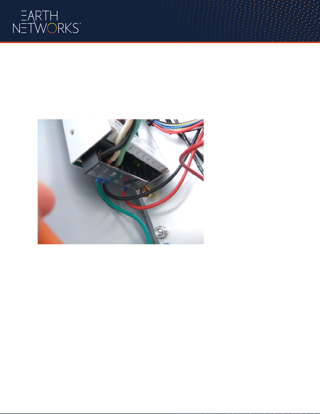
Power Connections (all horns)
This is an example of wiring the main power into the horn enclosure. Horns need to be hardwired by a
licensed electrician
Ensure that the wires are securely attached to the power supply mounting block and that bare wire is not
exposed. Replace plastic cover guard over the wiring block.
Horn Connections
Please refer to the wiring diagram found at the end of this manual.
1. The Red wire will connect to the Omron on the Left Side of Q0
2. The Black wire will connect to the ground block found on the left side of the main board.
Strobe Connections
Please refer to the wiring diagram found at the end of this manual.
The Red wire will connect to the Omron on the right side of Q1.
The Black wire will connect to the ground block found on the left side of the main board.
Data Connections (base horn only)
The base horn location will also require wiring the base horn to the Informer via a four wire data cable.
Wire Color
Informer Connection
Omron Connection
Signal
Blue
Yellow
Red
Black
Relay Out #1
Relay Out #2
Relay Out #3
Relay Out Com1-3
I0
I1
I2
(-) or Ground Bar
Pulses on Alert
Pulses on All Clear
Pulses on Cancel
Ground
Installing Informer
Informer Wiring
The Informer requires 120/240 VAC. The Informer will also need network access and will be connected to the
base site outdoor horn via a data cable.
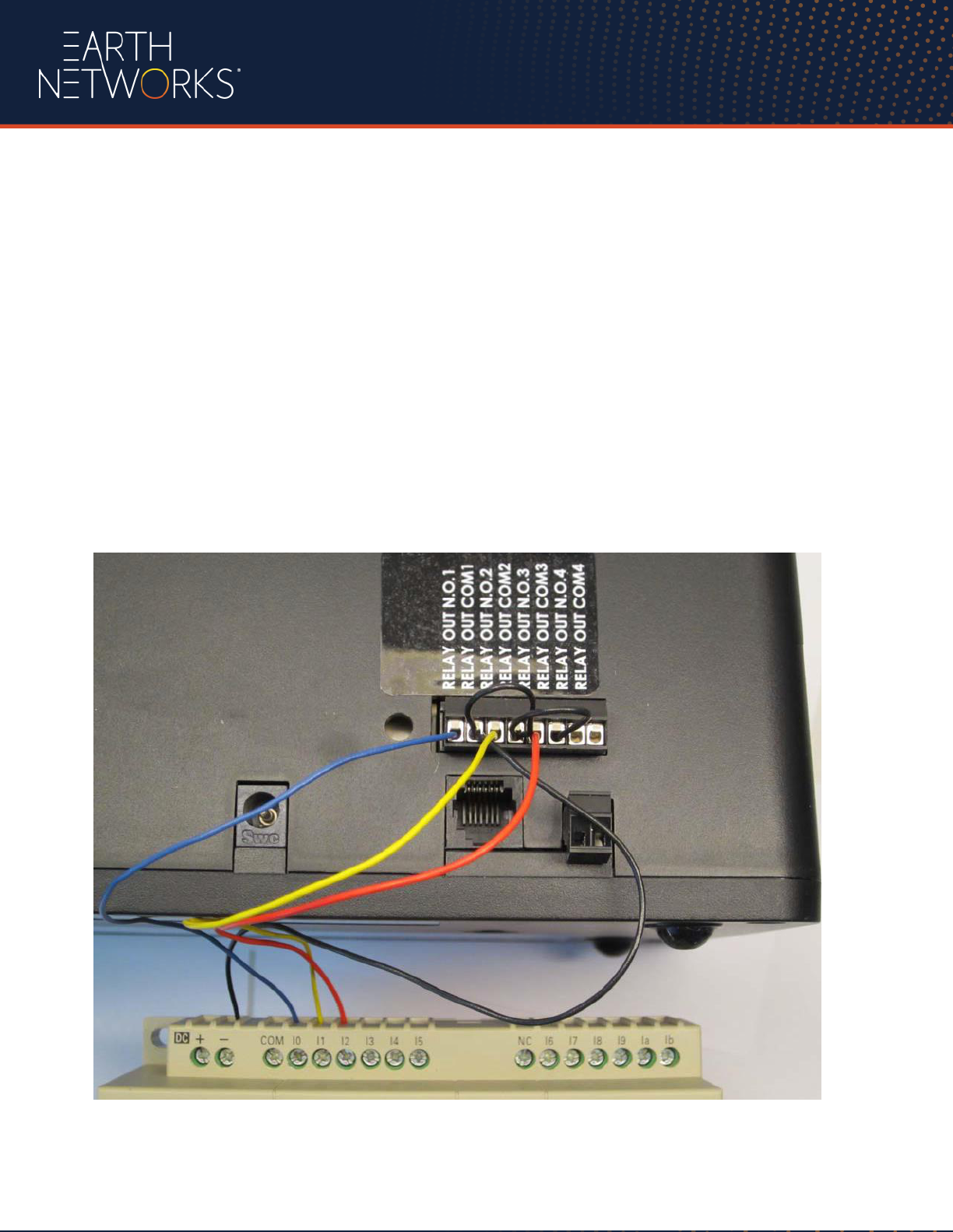
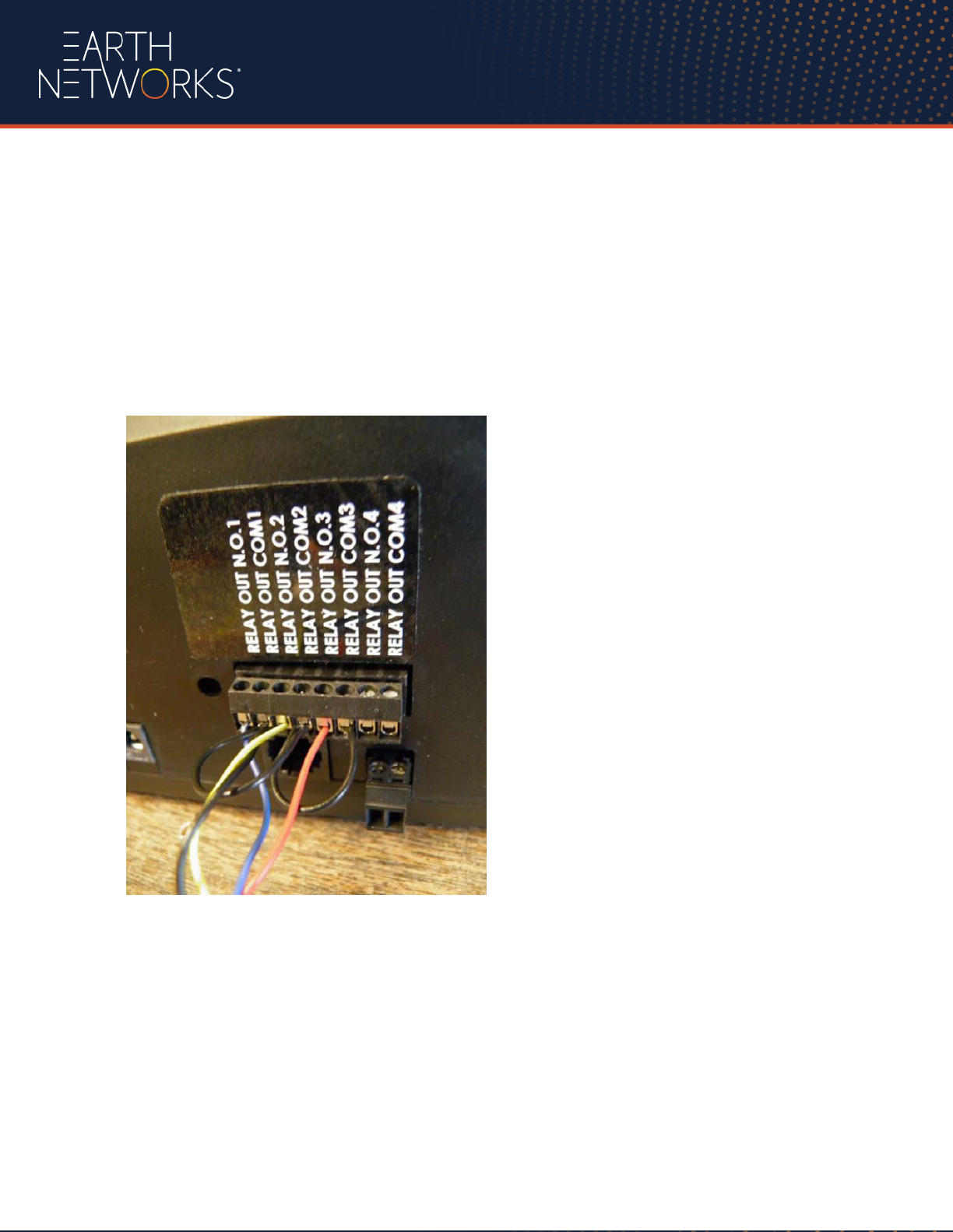
Data Cable Connections (example above)
Securely connect all data cable and jumper wires to the Informer as outlined below and the figure above.
Blue data cable wire - Relay out N.O. 1
Black data cable wire and 1 Black jumper wire - Relay out Com 1
Yellow data cable wire - Relay out N.O. 2
Black jumper from Relay out COM1 and another Black jumper – Relay out Com2
Red data cable wire - Relay out N.O. 3
Black jumper from Relay out Com2 - Relay out COM 3

Additional Informer Connections
Connect Ethernet cable to the back of the Informer.
Connect the Informer Power Supply into the wall receptacle.
Connect the power supply output connector into the Informer (power light should now be illuminated).
Configuration
Overview
Before using the Informer on your network, configuration must be performed by a System Administrator.
The Administrator must be familiar with IP network equipment and this manual. Proper configuration
settings are required for the network to be able to reliably communicate with the device and create a
redundant, failsafe network architecture for your system.
The Informer can use a static IP address or it can be configured for DHCP. The factory default setting
places the Informer in DHCP mode. The unit may be restored to this factory default setting with a hardware
reset if the configuration information is lost.
The default username / password are: User: config, Password: Informer-IP. The config user has security
rights to change the config user password. Usernames and Passwords are case sensitive.
Configuration via Web Browser Interface
Computer Configuration
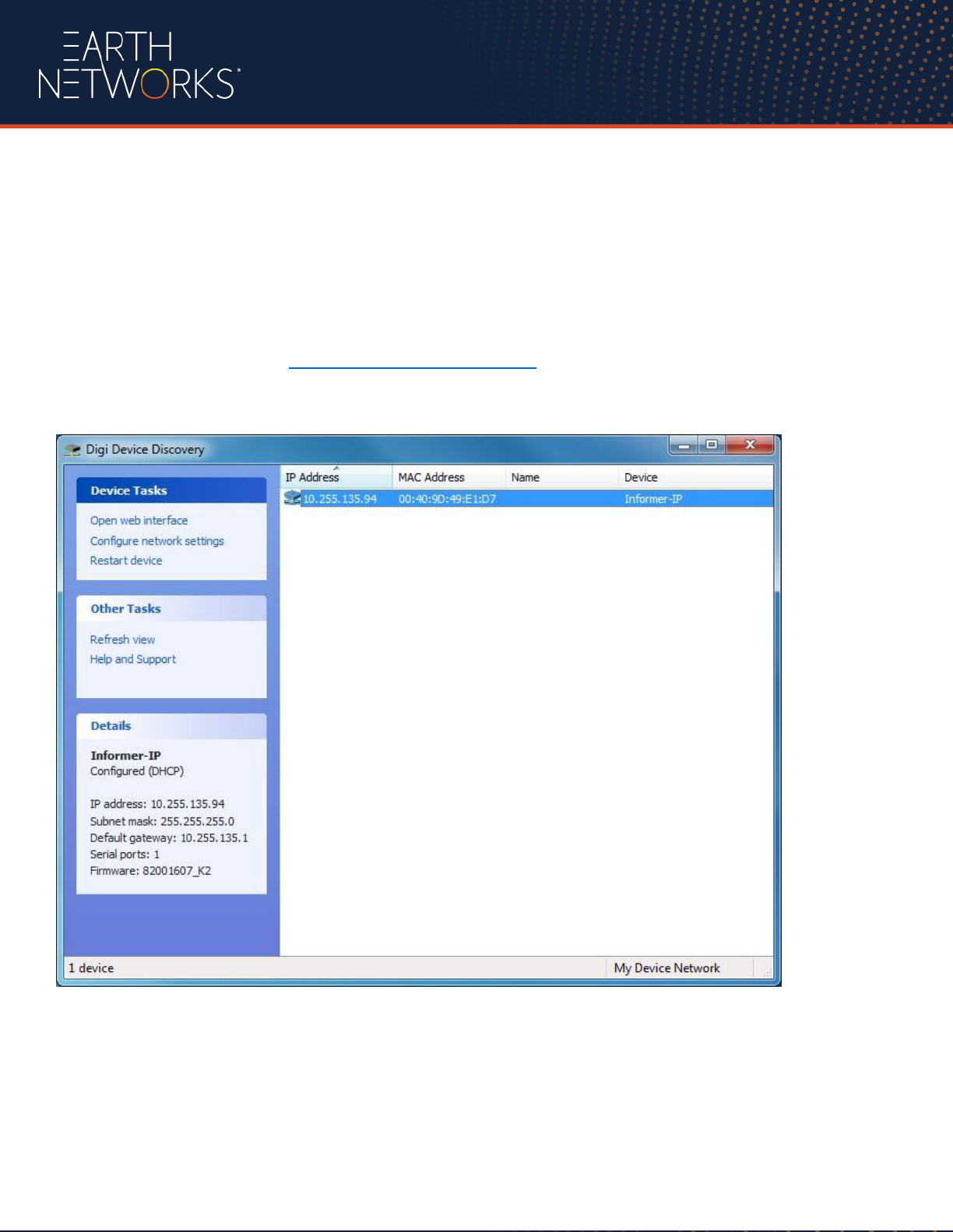
In order to connect to the Informer via the web browser the Digi device Discovery tool (dgdiscvr.exe)
must be downloaded from http://support.earthnetworks.com.
Once downloaded, run the tool to determine what IP address has been assigned to the Informer.
Double click your mouse on the Informer address displayed, and then proceed to Login
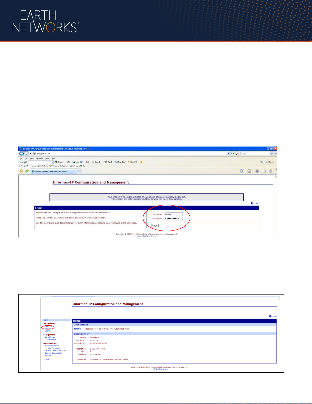
Login
After double clicking on the Informer IP address, the Login screen should be displayed
Enter the default username and password as follows:
Username: config (or pre-configured Username)
Password: Informer (or pre-configured Password)
Login to the Informer
System Server and Unit ID Assignment
Once the Home page is displayed, select System from the Configuration menu on the left
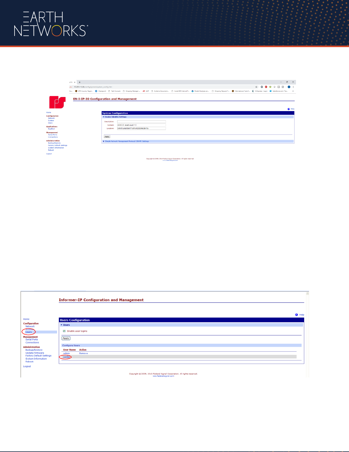
Enter 54647ca4a09d471c97c482824b53b17a into the Location field.
Change Config User Password
Change the Config user default password for security and store the new password and the network
configuration settings in a secure location. The default password and original configuration can be restored
by executing a Factory Default function. Select Users from the Configuration menu. Select the config user
to change the password. Enter the New Password, Confirm and apply the new password.
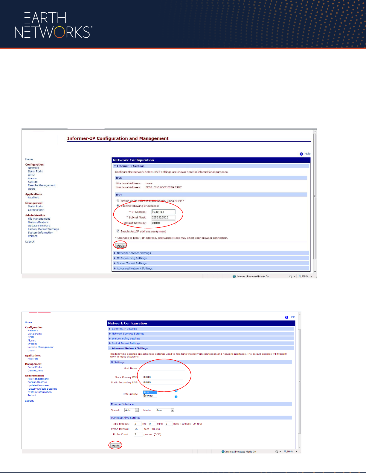
Static IP Address, Site ID, and Location Assignment
Click on the Network menu item and select: “Use the following IP address”
Enter the static IP address; Subnet mask and Gateway for the Informer. Select “Apply” once entries
are complete.
Select Advanced Network Settings to provide a host name and configure DNS servers. Select “Apply”
once entries are complete.
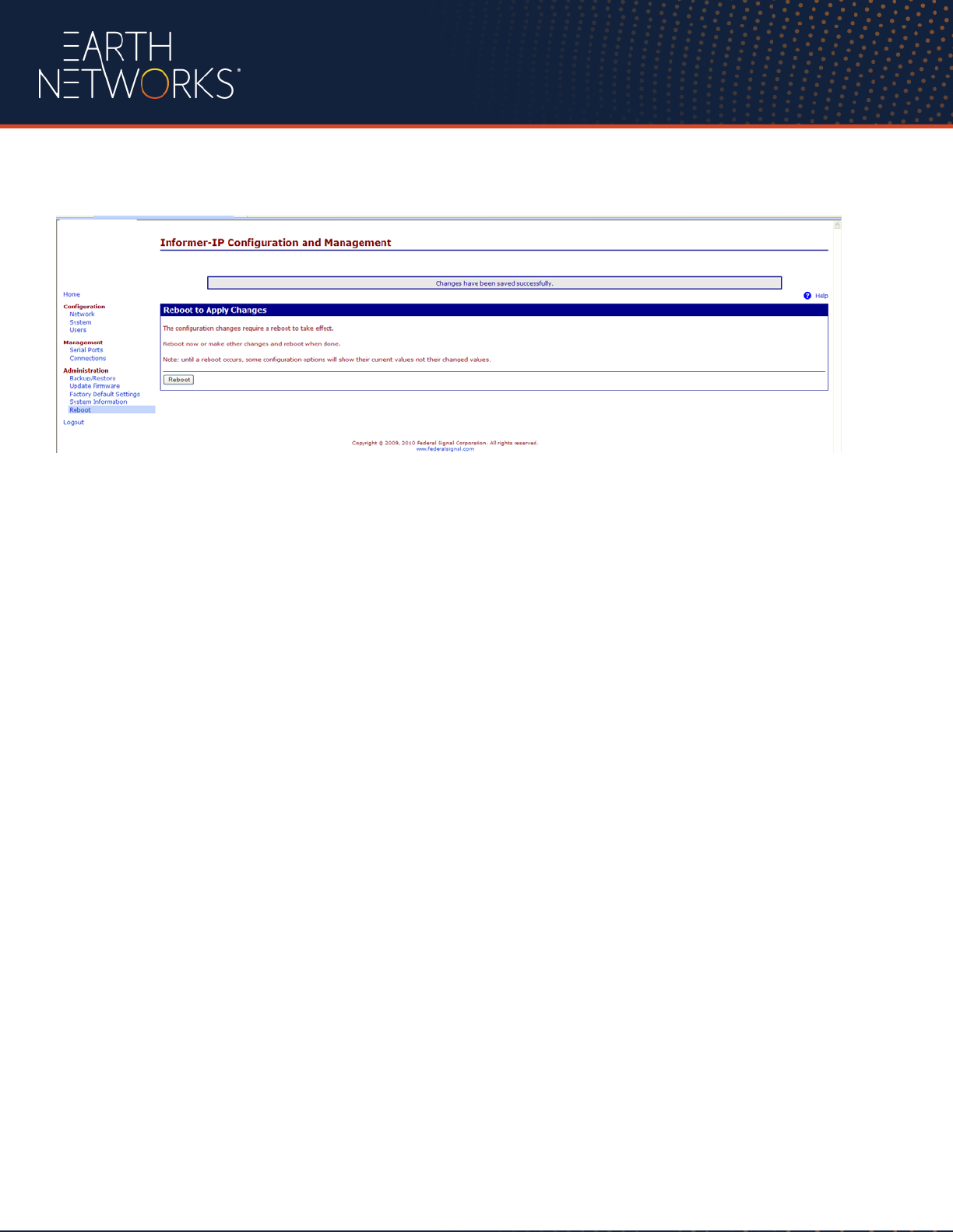
The device must be rebooted for the IP address change to take effect using the Reboot menu item.
Verify that the IP address is change was successful by running the Digi Device Discovery tool again. You
should see that the correct IP address is now showing. Place the Informer on your network and bring up
your web browser. Type in the new IP address for your Informer, the Login screen should appear. Log in
and verify that all of your settings are correct.
Backup Configuration
Once all configuration settings are complete, configuration settings can be backed up and restored using the
Backup/Restore menu selection.

Informer Operating Instructions
General Information
The Informer must be configured correctly and tested before placing into service. Refer to the
configuration section of this manual. If you are experiencing any difficulties with the Informer, contact
your local Earth Networks service representative.
The following sections describe the various features and functions of the Informer.
LED Indicators
Power LED
The green power LED will turn on when power is connected.
Alert LED
The red Alert LED will Flash on and off at a 1 second interval when an Alert is received. The LED is
reset when the All Clear or Cancel buttons are pressed or the Earth Networks server ends the Alert.
Trouble LED
The yellow trouble LED will turn on when the Alert Controller loses the connection to the Earth Networks
Server.
Test LED
The Blue Test LED turns on Steady when a Test alert is received from the Earth Networks server. The
Test LED will stay on for 10 minutes. This feature is useful to ensure the user can communicate with
the Earth Networks server and that the Alert Console is receiving messages from the Earth Networks
server.
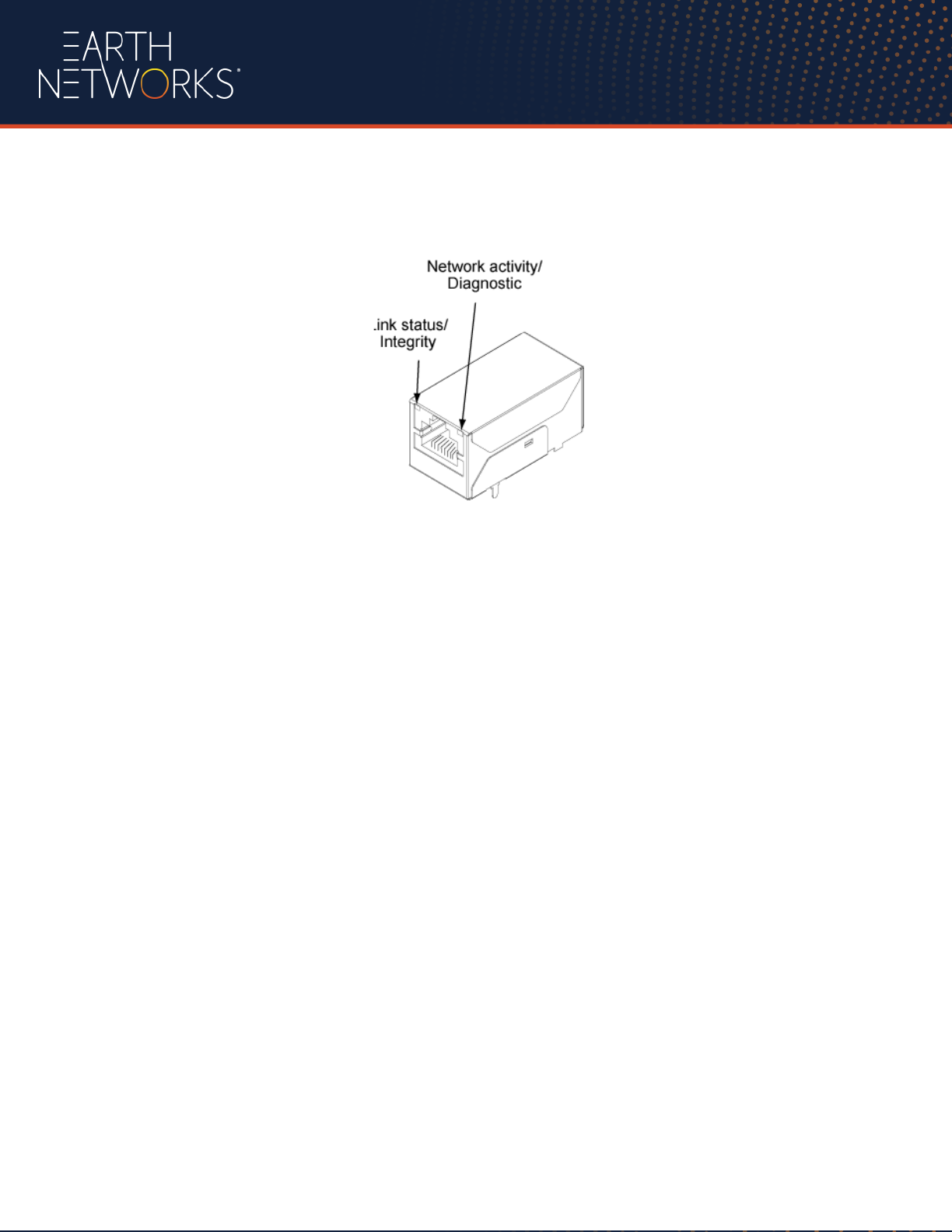
Network LEDs
The Ethernet port has two diagnostic LED s.
Yellow - Link Status
Off - no link has been detected.
On - a link has been detected
Green - Port Activity
Off - the channel is idle.
Blinking - data is transmitted or
received.

Keypad
The Informer includes a 5-button keypad and 4 diagnostic LEDs.
Volume Adjustment
To adjust the volume, press the VOLUME ↑ button to increase the sound volume. Press the VOLUME
↓
button to decrease the volume. A beep will be heard indicating the current volume level each time the
volume buttons are pressed.
ALERT Button
The Alert button allows the operator to manually initiate an Alert. The Alert will be initiated at the
Informer and activate all outdoor horns. The red Alert LED will light indicating that the Alert is active.
The Alert will sound a 15 second horn blast and turn on a strobe light, on each horn, for the duration of
the Alert.
ALL CLEAR Button
The All Clear button allows the operator to manually initiate an All Clear. The All Clear will be initiated at
the Informer and activate the outdoor horns. The All Clear will turn on the strobe and sound three 5 second
horn blasts then turn off the strobe and the Alert LED to indicate the Alert has ended.
CANCEL Button
The Cancel button ends the Alert Function turning off the strobe and Alert LED. The horn will not sound
an all clear signal when the alert it cancelled with this button. The Cancel button can only be used to cancel
manually initiated Alerts. The Earth Networks Alert Control System will automatically re- initiate alerts
that have been manually cancelled. The 15 second horn blast will occur each time an alert is re- initiated.
Testing and Training
After the installation is complete, test the Informer and Alerting Horns to ensure the system is operating
properly. Ensure all users are properly trained to use the system prior to putting the Informer into service.
Testing should be conducted on a regular basis per facility safety plans to ensure the equipment
remains in working order and operators remain familiar with the use of the equipment

Troubleshooting
Informer Trouble Light is illuminated
•
Check to see if other devices on the same network as the Informer are having problems.
•
Verify that the LAN cable is securely connected to the Informer and the Network Device (switch/router).
•
Verify that the Informer is properly configured.
No lights on the Informer
•
Verify that the Informer power supply is fully seated into the outlet and the back of the Informer.
•
Verify that the outlet for the Informer has power.
Informer sounds, but some or all outdoor horn(s) do not
If the base outdoor horn didn’t sound
•
Verify that the horn controller has power.
•
Verify that the data cable connections at the horn controller and the Informer are properly connected.
•
Verify that the horn is connected to the controller box.
Base outdoor horn sounds but optional horn(s) do not
•
Verify power is on within the controller box.
•
Verify that the horn is connected to the controller box.
If the problem persists contact Earth Networks Technical Support (800) 624-
4205 or [email protected]
Restore Configuration to Factory Defaults
If the configuration details are lost or changed incorrectly and it becomes necessary to restore the
Informer to factory default settings, a Power-On Factory Default procedure may be performed as
follows:
1. Remove power from the Informer.
2. Press and hold down the Reset button.
3. Apply power while holding down the Reset button.
All local configuration settings will need to be re-entered before placing the Informer into service

Maintenance
There is little maintenance needed for the Outdoor Alerting System as long as power and internet
connectivity are maintained and the outdoor controller cover is tightly fastened.
Periodic inspections should be performed on outdoor components to ensure data and power cables are
secure and undamaged. The outdoor controller should be inspected to verify it remains water-tight.
Additional Information
This product has been designed with safety in mind. However, if not properly installed and used, any
electrical product can cause fires. To avoid such incidents, please be sure to follow these guidelines.
•
Follow all general safety precautions
•
In case of a system breakdown, discontinue use, unplug the unit and all other cables, and contact
Earth Networks Technical Support at (800) 624-4205 or email [email protected]
•
In case of abnormal operation (Unit is emitting smoke or an unusual smell, water or other foreign
objects enter the housing, the unit is dropped or damaged et. al):
o Disconnect the power cable and other connecting cables.
o Contact Earth Networks Technical Support at (800) 624-4205 or email

Specifications
Informer Specifications
Item
Specification
Audio Frequency Response
300 Hz to 3000Hz, +1 to -3dB per octave
Audio Output
½ watt into 8 ohms
Audio Distortion
< 5% @ 80dB, with 700 Hz tone
Ethernet Port
IEEE 802.3, 10/100 base-T Full/half Duplex auto-negotiating
Relay Outputs
Four Normally Open Relay Outputs, 5 amps @ 30VDC
Electro Magnetic Interference
Complies with FCC Title 47, Part 15
Operating temp range
-22F + 140F/ -30C + 60C
Tilt Speed
400 degrees/s (max.)
Power Requirements
120 VAC w/wall transformer
Power Consumption
5 amps
Dimensions
8” W x 5” D x 3.5” H/ 215.9mm x 127mm x 88.9mm
Weight
Approximately 2.8 pounds / 1.27 kg
Horn Specifications
Item
Specification
Enclosure
NEMA Type 4X, IP66
Power Supply AC Input
85-264VAC, 47-63 Hz/ 3.5A@115VAC, 1.7A@230VAC
Power Input DC
20 to 28 VDC, 70 ma Standby, 4A with horn and strobe
Power Supply DC Output Voltage
22-28 VDC
Power Supply DC Output Current
8.4 amps DC max
Battery Backup
5 days without AC power
Strobe Light Output
175,000 Candela Peak
Flash Rate
65-95 / minute
Horn Acoustic Output
117dB Omni-directional
Horn Current
3 A
Mounting
1.5” pipe
Wind Load
142lbs (@110mph,30’)
Dimensions
39” x 12” x 23.5” H/ 991 mm x 305mm x 597 mm
Weight
50 lbs, 22.7 kg (without 1.5” pipe)
Operating Temperature Range
-40° to +122° F / -20° to + 55° C
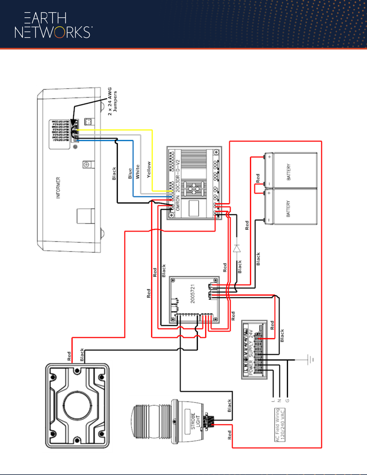
Wiring Diagram
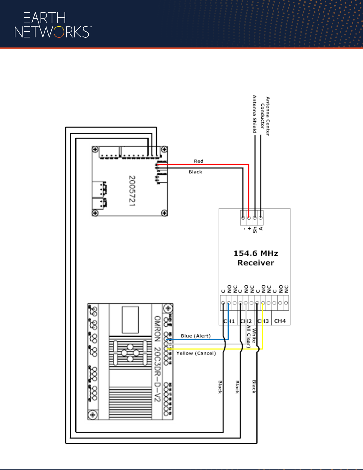
Optional Radio Wiring Diagrams
Receiver Diagram
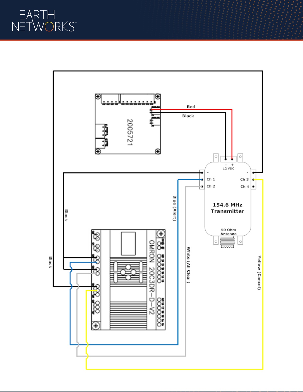
Transmitter Diagram
