Graphical
Forecasts
for
Aviation
Developed
by
Terry T. Lankford
(FAA FSS Retired; CFII; FAASTeam Representative;
National Weather Association
Aviation Meteorology Committee)
User’s Guide
September 2018
The Federal Aviation Administration (FAA) and National Weather Service (NWS) have stated:
“There probably is no better investment in personal safety, for the pilot as well as
the safety of others, than the effort spent to increase knowledge of basic weather
principles and to learn to interpret and use the products of the weather service.”
Each forecast is based on its scope and purpose in accordance with specific criteria, and has
limitations. An understanding of format, scope, purpose, limitations, and amendment criteria are
required to adequately apply a forecast, particularly when using a self-briefing media.
Graphical Forecasts for Aviation
In 2018 the Graphical Forecasts for Aviation (GFA) replaced the legacy text Area Forecast (FA)
in the contiguous United States. The GFA can provide more localized areal coverage and a tem-
poral resolution of one hour—surface to FL480.
SCOPE: A mostly synoptic scale product, the GFA describes conditions produced by
weather systems such as high and low pressure areas, air masses, and fronts. The
GFA typically predicts conditions that may affect flight operations over relatively
large areas.
PURPOSE: The GFA provides a forecast for the enroute phase of flight and for locations
without a Terminal Aerodrome Forecast.
LIMITATIONS: The GFA is not intended to cover every phenomena. Events predicted
in other products might not appear. The Graphical Forecasts for Aviation suite
includes most weather advisories, requires users to view several pages to obtain
pertinent data, and can suffer from clutter.
The National Weather Association’s Aviation Meteorology Commit-
tee has developed Weather Theory for Pilots; an interactive program
designed to help General Aviation pilots better understand and apply
weather theory and technologies to their flying activities. Although, spe-
cifically intended for new or low-time pilots, blocks and modules provide
those without formal recurrent programs with refresher training in fun-
damental weather principles and their application to flight operations.
The program is available at:
nwas.org/weather-theory-pilots-line-course/
Send comments, suggestions, and questions to:
Terry T. Lankford
231 Snowberry Ct.
Murphys, CA 95247
e-mail: [email protected]
3
The Aviation Weather Center (AWC) has been developing a graphical replacement for
the text Area Forecast (FA)—at least conceptually—for over a decade. In June 2014
the Federal Aviation Administration (FAA) and National Weather Service (NWS) an-
nounced a request for comments to transition to digital and graphical products. “The
experimental Graphical Forecasts for Aviation is intended to provide the necessary
aviation weather information to give users a complete picture of the weather that may
impact flight in the continental United States.” The Graphical Forecasts for Aviation
(GFA) is a digital product for commercial and general aviation pilots, operators, brief-
ers, and dispatchers. In the spring of 2016 the experimental GFA became available
on the AWC’s web site (www.aviationweather.gov). Since then the product has gone
through several incarnations. The Graphical Forecasts for Aviation became operation-
al in April 2017. Text Area Forecasts for the contiguous (CONUS) United States were
discontinue in October 2017.
The Graphical Forecasts for Aviation suite provides the most complete set of graphi-
cal weather reports and forecasts. The AWC produces Aviation Surface and Aviation
Clouds Forecast graphics as a low-bandwidth alternative to the GFA. These static
images provide graphical forecasts for Flight Service (Leidos) and other users/vendors
with limited Internet. Access these products from the AWC’s web site—see callout.
This Guide provides a condensed description of the GFA. Its purpose: Provide users
with methods to obtain forecast data previously available from the text Area Forecast.
Appendix 1: Application provides operational use and limitations of the product.
Appendix 2: Explanation/Definitions contains additional clarification and descriptions
of terms and symbols. (For further details refer to the AWC’s web site; “click” the infor-
mation (INFO) tab on the “GFA Tool” page.
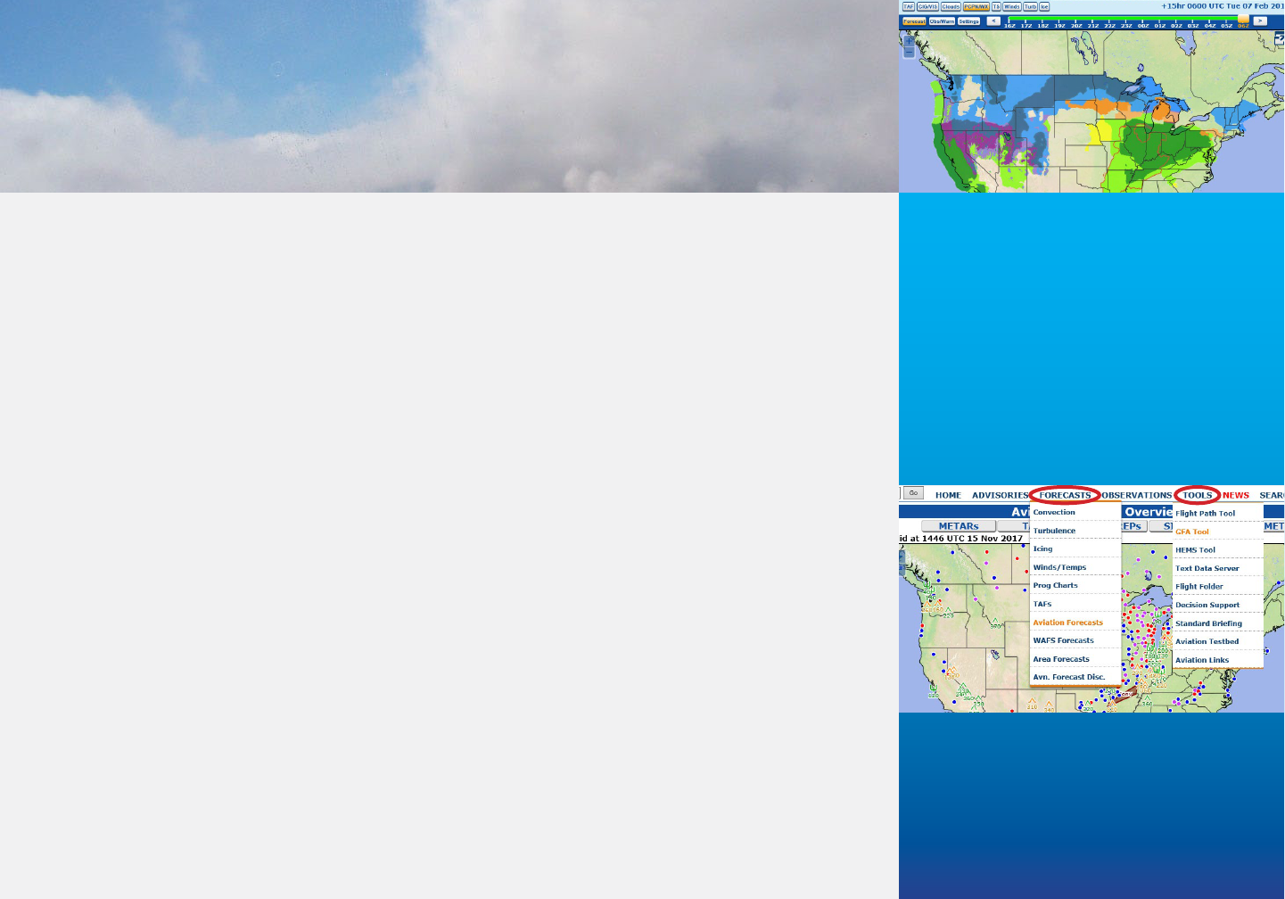
Products are available on the AWC’s
“Home Page:” For Aviation Surface
and Clouds use the top menu under
“FORECASTS” select “AVIATION
FORECASTS;” for the GFA Suite use
the top menu under “TOOLS,” select
“GFA Tool.”
Graphical Forecasts
for Aviation
4 Graphical Forecasts for Aviation
Display
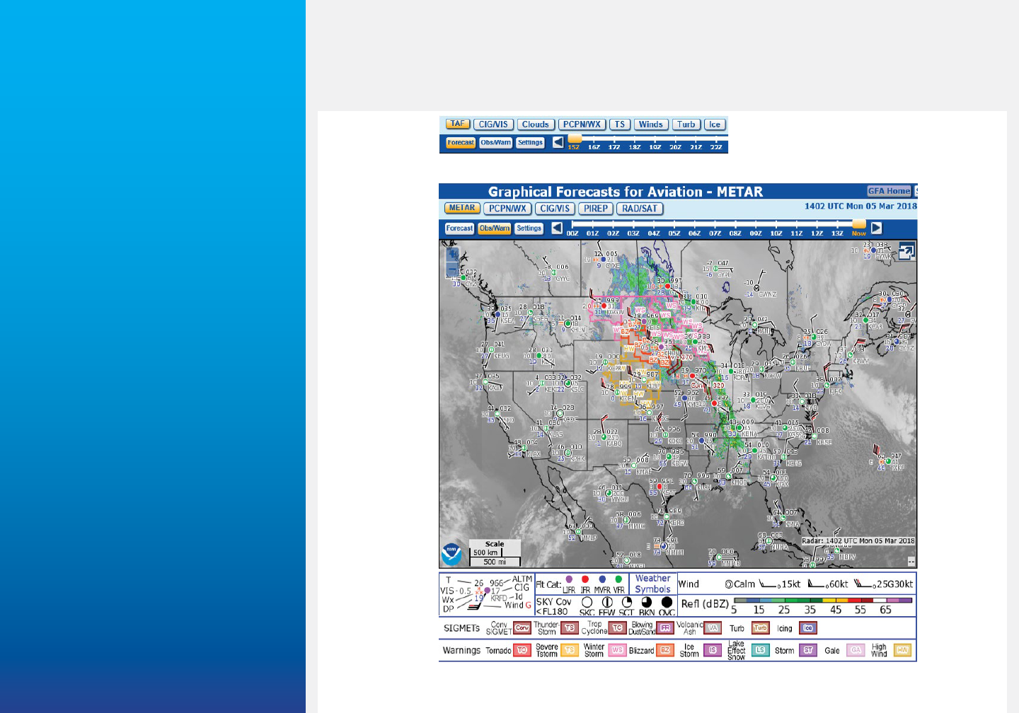
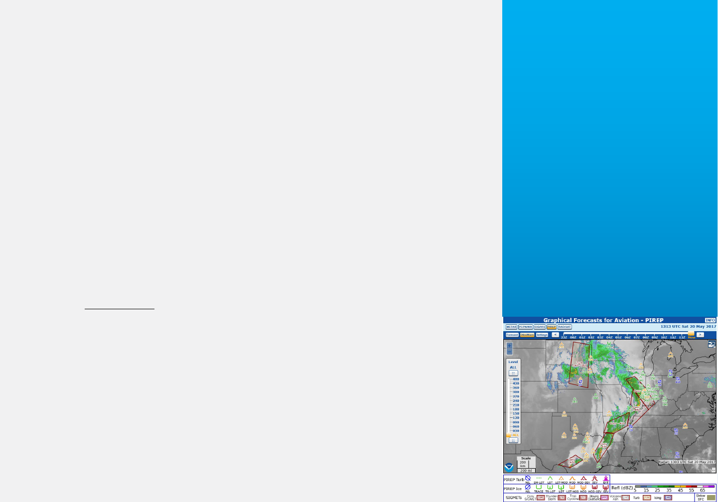
The GFA page, shown in Fig. GFA-1, contains a MENU BAR, PRODUCT VIEW AREA,
and LEGEND. The MENU BAR incorporates Weather Product and Function Buttons,
and Date/Time Display.
Fig. GFA-1. The GFA page consists of a Menu Bar—Weather Product and Function
Buttons, Product View Area, and Legend.
MENU BAR
Weather Product
Function Buttons
Weather Product
(Forecast Options)
Function Buttons
Date/Time
Display
LEGEND
PRODUCT
VIEW
AREA
Zoom
“+/-”
Full Screen
Graphical Forecasts for Aviation 5
Menu Bar
The MENU BAR (Fig. GFA-1) consists of a series of Weather Product and Function
Buttons. Weather Product Buttons and Date/Time Display differ for the “Obs/Warn”
Functions (Fig. GFA-1) and “Forecast” (top inset). The LEGEND changes to reflect the
Weather Product displayed.
The Date/Time Display, right side of MENU BAR (Fig. GFA-1), provides the date and
time of the product. The Slider Bar allows selection of a specific hour (UTC). “Click” the
back/forward arrows or “drag” the box on the top of the Slider Bar. “Obs/Warn” prod-
ucts are available to 14 hours in the past; “Forecast” products are available up to 15
hours with a temporal resolution of one hour.
Like the G-AIRMET, the GFA provides a “snap shot” of expected conditions
at specific times. Similar to the TAF BECMG change group, phenomena will
change at either a regular or irregular rate at an unspecified time within the
period. Avoid interpolating between time frames.
Product View Area
The PRODUCT VIEW AREA incorporates zoom, full screen mode, drag, and cursor and
NAVAID position functions.
“Zoom” PRODUCT VIEW AREA using the “+/-” buttons in the upper left corner (Fig.
GFA-1) or mouse scroll wheel. (On a tablet, “pinch” zoom.) Hold the shift key while
pressing the left mouse button to select a zoom region—enclosed by a “red” box (call-
out). The higher the zoom level, the more stations plot. Product density increases with
“Zoom.” “Click” CONUS on “Settings” (Fig GFA-2 under MAP; Map Domain) to return
coverage to the continental U.S.
Select full screen mode with the “full screen” button in the upper right part of the dis-
play (Fig. GFA-1). The menu bar remains at the top. (A “show legend” button appears
Warning
Signicant material is highlighted as
a “Caution” or “Warning” in the text.
“Potential hazard” should know
information.
“Signicant hazard/regulatory” must
know information.
Warning
Caution
6 Graphical Forecasts for Aviation
to display appropriate legends.) Press “full screen” again to return to normal view.
“Click” the left mouse button in the PRODUCT DISPLAY AREA and drag to “Pan” the
map. (On a tablet, touch and drag the display area.)
Legend
The LEGEND, at the bottom of the page decodes displayed products. Appendix 2 pro-
vides additional details on WARNINGS contractions, symbols, and definitions.
Note
All heights are Mean Sea Level (MSL), except TAFs, METARs and the CIG/
VIS Weather Product—CIG grid.
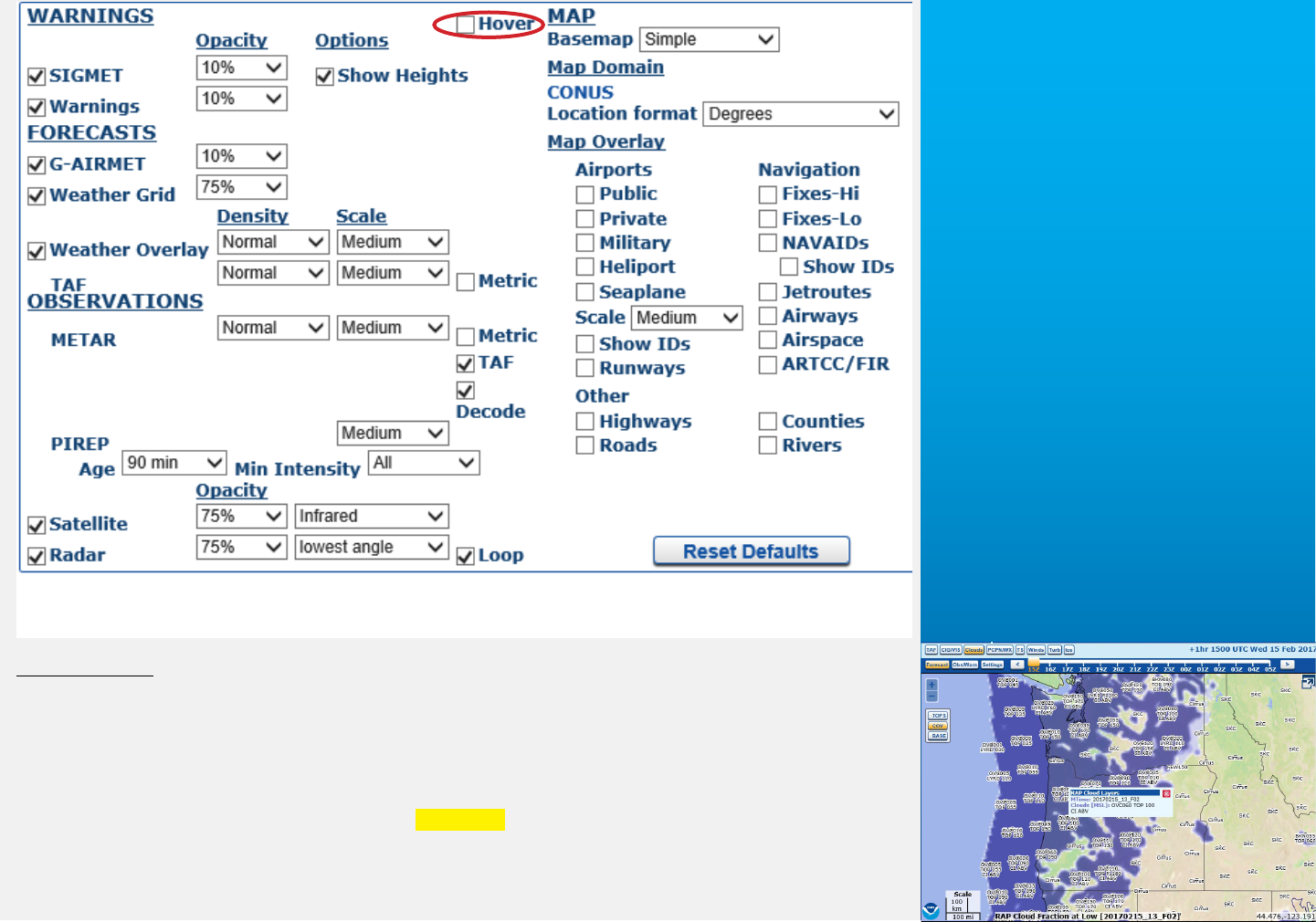
Settings
The “Settings” Function Button provides DISPLAY VIEW AREA product custom-
ization. “Settings,” shown in Fig. GFA-2, is divided into four areas: WARNINGS,
FORECASTS, OBSERVATIONS, and MAP. Within each area “check” boxes enable/
disable products, and control opacity, density, scale, and other functions. The “Hover”
check box—top, center of “Settings,” activates/deactivates the “Hover” function. In the
PRODUCT VIEW AREA “Click” or “Hover” an observation, forecast, grid point, weath-
er symbol, or polygon to display “pop-up” text—see callout.
WARNINGS controls the display of NWS Warnings, Domestic and International
SIGMETs, and AIRMETs. (Appendix 2: Explanation/Definitions, Table GFA A2-1 pro-
vides expanded WARNINGS type, contractions, symbols, and definitions.)
At present, Center Weather Advisories (CWA) are NOT displayed. SIGMETs/
Convective SIGMETs only display during the valid time of the product. When
SIGMETs continue beyond (CONTG BYD) their valid time (four hours) or
Convective SIGMETs continue (beyond two hours) into their OUTLOOK peri-
od the SIGMET is NOT displayed.
Warning
Graphical Forecasts for Aviation 7
FORECASTS controls the display of G-AIRMETs, Weather Grid and Weather Overly
products. The Weather Grid consists of “computer model” generated depictions of
graphical coverage of ceilings/visibilities, and coverage and probability of precipitation,
cloud—coverage, bases, tops, and turbulence, icing, and winds. The Weather Overlay
depicts weather symbology, Winds barbs, and Clouds point forecasts (callout).
Weather Overlay symbology, Winds barbs, and Clouds point forecasts may
NOT represent adjacent conditions. Weather between points may be substan-
tially different, especially in mountainous areas.
Fig. GFA-2. The “Settings” Function Button allows user customization of the Weather
Products in the PRODUCT VIEW AREA.
Caution

8 Graphical Forecasts for Aviation
OBSERVATIONS tailor METAR, PIREP, Satellite, and Radar displays.
Customize TAF and METAR display density and scale using Density setting—least to
most; Scale data icons—Tiny to Huge. Display text in raw format, decode, or metric.
MAP modifies Basemap, Map Domain, and Map Overlay. A “Reset Defaults” button
appears in the lower, right of “Settings.”
Forecast
“Forecast” Weather Products consist of:
• TAF—Terminal Aerodrome Forecasts
• CIG/VIS—Ceilings/Visibilities
• Clouds
• PCPN/WX—Precipitation/Weather
• TS—Thunderstorms
• Winds
• Turb—Turbulence
• Ice
TAF—Terminal Aerodrome Forecasts
Station plots display TAFs valid for the selected time using standard station models.
(Appendix 2 provides further explanation of station models.)
CIG/VIS—Ceilings/Visibilities
Select FLT CAT (Flight Category), CIG, and VIS grids using the tabs in the upper left
corner of the display. Flight Categories (LIFR, IFR, MVFR) are color coded.
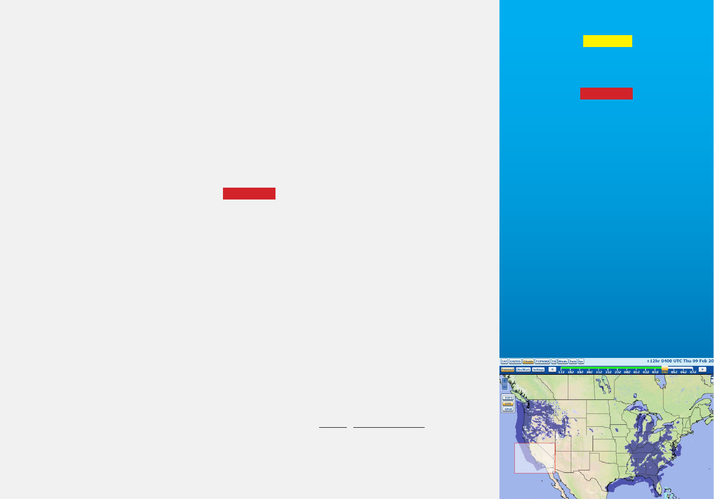
Clouds
Select Cloud TOPS, COV (Coverage), and BASE grids using the tabs in the upper
For additional detail see Forecast
page depictions in Appendix 1:
Using the GFA.
TAF depiction is similar to the Obs/
Warn METAR page in Fig. GFA-1.

Graphical Forecasts for Aviation 9
left corner of the display. The LEGEND decodes coverage, bases (3000 ft increments
through 18,000 ft), and tops (3000 ft increments through 18,000 ft/6000 ft increments
through FL480). CI indicates cirrus type clouds above FL180.
Note
The Rapid Refresh Model (RAP) Low Cloud Tops overlay grid displays clouds
below FL180. For convective tops see Convective SIGMETs (WST), convective
Center Weather Advisories (CWA), Aviation Watch Notification Messages
(AWW), Severe Thunderstorm/Tornado Watch Notification Messages (WW),
and the Convective Outlook (AC).
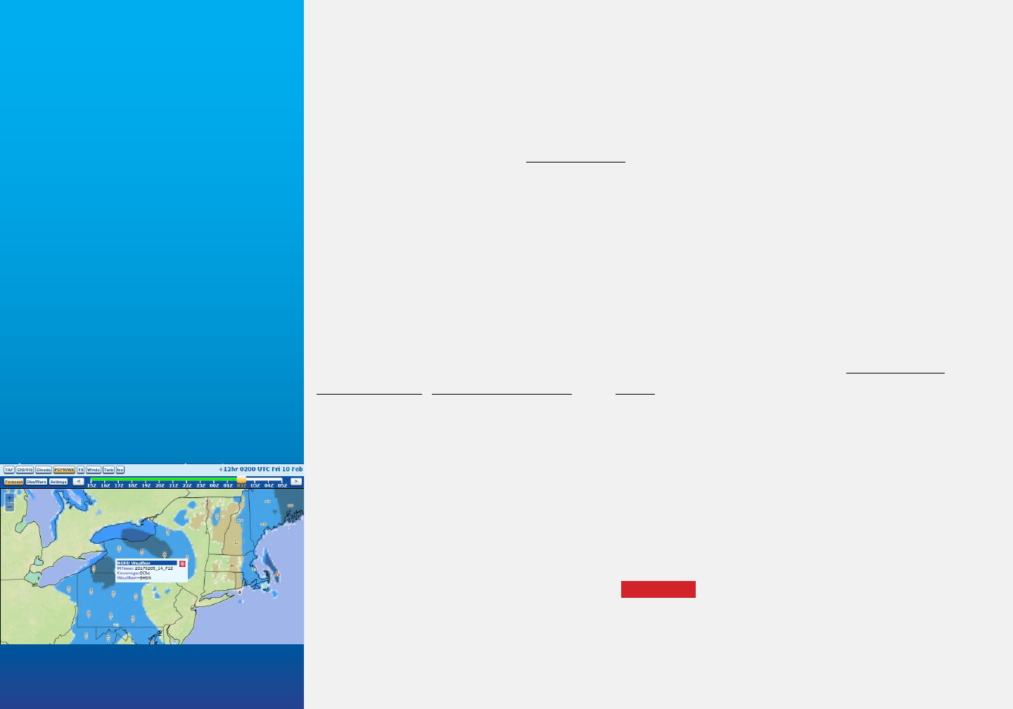
PCPN/WX—(Precipitation/Weather)
The Weather Grid depicts precipitation and weather type, and probability. The
Weather Overlay provides precipitation and weather symbols—coverage and probabili-
ty. Appendix 2 provides additional details on weather type, coverage, and probability.
TS—Thunderstorms
The Weather Grid depicts thunderstorm coverage. The Weather Overlay provides
precipitation and weather symbols—coverage and probability.
Note
Winds, Turb (Turbulence), and Ice pages provide height data from the sur-
face to FL480—3000 ft increments through FL300 and 6000 ft increments
through FL480. Brown shading indicates levels below the surface.
Winds
The Level Selection Bar provides wind speed and direction for specific levels, “MAX”
(maximum), and “SFC.” G-AIRMET Tango displays “surface winds” and “low-level
wind shear” advisories.
10 Graphical Forecasts for Aviation
The Graphical Turbulence Guidance product has limitations and must be
used along with turbulence forecasts provided in AIRMETs, SIGMETs, and
Center Weather Advisories. The Forecast Icing Product is NOT a substitute
for icing information contained in AIRMETs, SIGMETs, and Center Weather
Advisories.
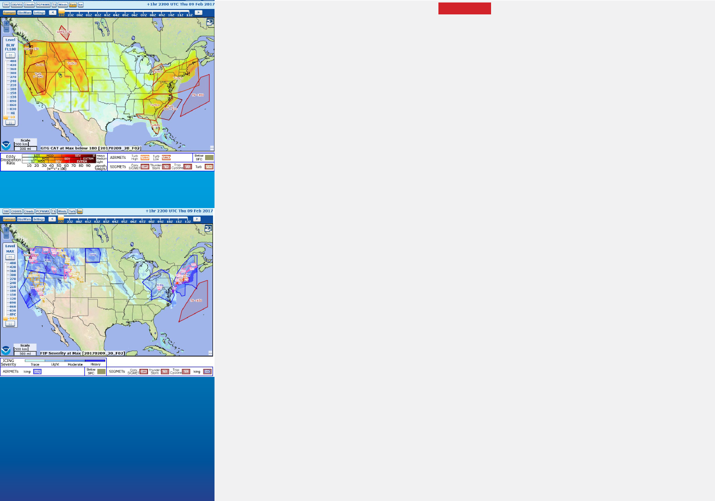
Turb—Turbulence
Weather Grid turbulence intensities are based on Eddy Dissipation Rate (EDR) from
the Graphical Turbulence Guidance (GTG) product. Select desired altitude from the
Level Selection Bar, or “LO” (below FL180) or “HI” (at and above FL180)—callout.
Ice
Weather Grid icing intensities are based on the Forecast Icing Product (FIP). The Level
Selection Bar displays “MAX” (maximum icing severity). “SFC” displays Weather Grid
winter precipitation and Weather Overlay symbols—callout.
Note
On the FIP none, trace, light, moderate, and heavy refer to the severity of the
meteorological icing environment—An atmospheric set of conditions where
the rate of ice accumulation is objectively defined, as opposed to subjective
observations (pilot) of the rate of ice accumulation and its effects on aircraft
performance.
Obs/Warn
“Obs/Warn” (Observations and Warnings) consist of:
• METAR
See the AWC’s Turbulence/Icing
pages for further explanation of
these products.
Warning
Graphical Forecasts for Aviation 11
• PCPN/WX—Precipitation and Weather
• CIG/VIS—Ceilings and Visibilities
• PIREP
• RAD/SAT—Radar and Satellite
METAR
METAR displays standard station model plots valid for the selected time. “Settings”
customizes the display. “Click/Hover” a station to display METAR and TAF text. An
example of the METAR page is shown in Fig. GFA-1.
PCPN/WX—Precipitation and Weather
PCPN/WX displays Weather Symbols. Other features are customizable in “Settings.
“Click/Hover” a station to display associated METAR and TAF text.
CIG/VIS—Ceilings and Visibilities
Using the menu at the top, left of the PRODUCT VIEW AREA, CIG/VIS displays color
coded flight category, and ceiling or visibility numerical values. (NWS Dense Fog and
Freezing Fog WARNINGS may be added in the future.)
PIREP
The Vertical Levels bar allows selection of PIREPs at and below specified altitude—
callout. Customize PIREP Age, Min (Minimum) Intensity, and Scale in “Settings. The
LEGEND decodes turbulence and icing intensities symbols.
RAD/SAT—Radar and Satellite
RAD displays a 40 minute loop of five images; intensity levels are shown in the
LEGEND. Select SAT imagery type—5km visible, 10km infrared, or water vapor in
“Settings.” (The callout illustrates the depiction of RAD/SAT imagery.)
12 Graphical Forecasts for Aviation
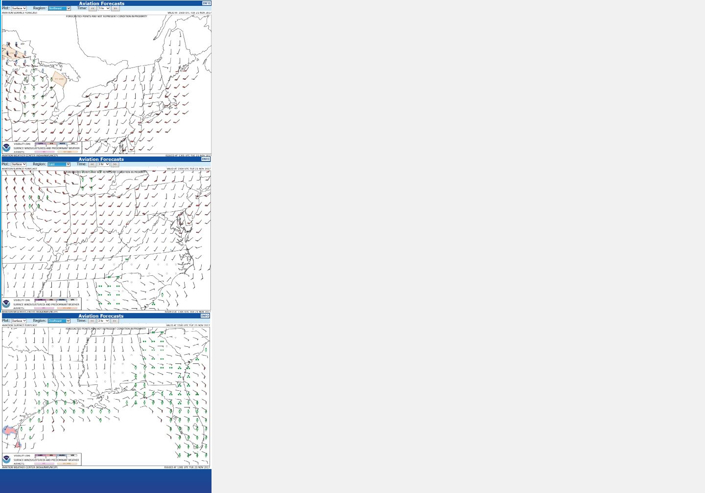
Aviation Surface Forecast and Clouds Forecast Graphics
Available from the AWC, FSS, DUATS, and commercial providers, 3 hour static images
contain forecasts out to 18 hours. Graphics cover the lower 48 states (CONUS) with 9
selectable regions. (See callout for western regional coverage.)
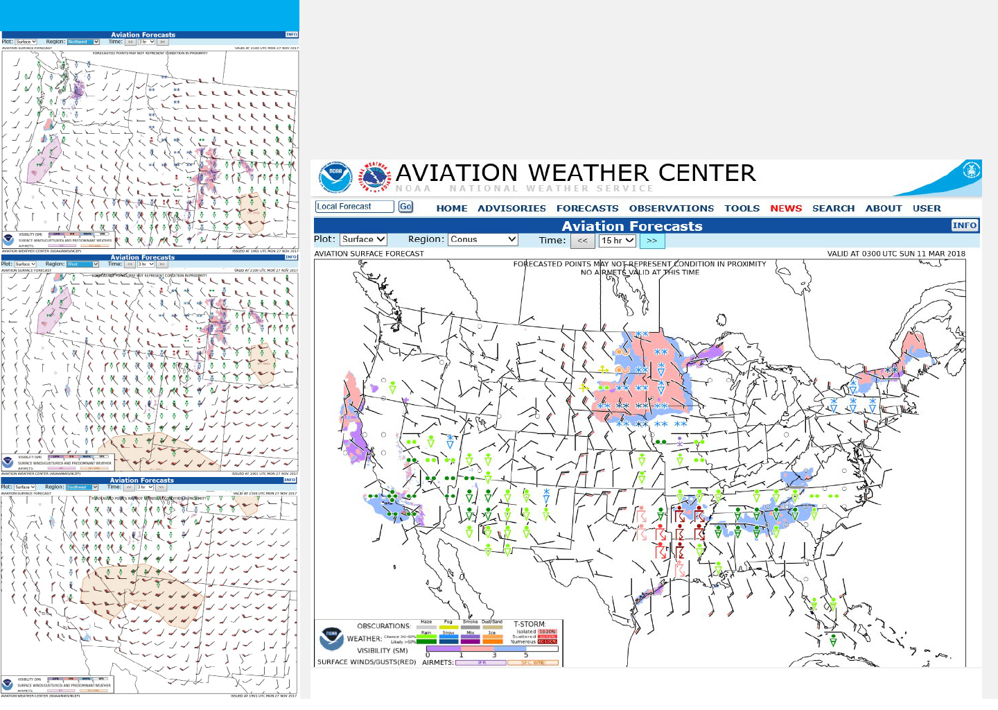
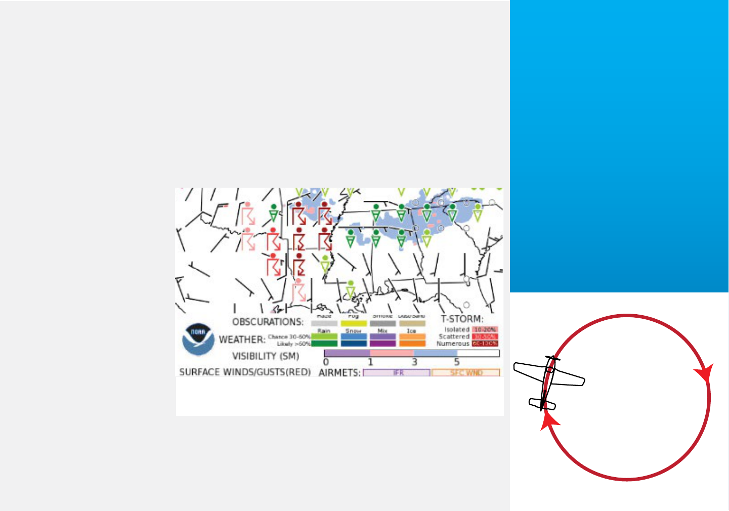
Fig. GFA 3 illustrates the CONUS Aviation Surface Forecast graphic. It contains a
Fig. GFA 3. Three hour static images include overlaid AIRMETS SIERRA (IFR),
and TANGO (Strong Surface Winds).
Graphical Forecasts for Aviation 13
categorical grid of surface visibility (LIFR, IFR, MVFR, and VFR); surface wind and
gusts, and predominant precipitation and weather type symbology. (Refer to Appendix
2 for Flight Category definitions; and, Fig. GFA A2-1 Station Model Symbols and Table
GFA A2-3 Weather Symbols.) Graphical AIRMETS SIERRA (IFR), and TANGO (Strong
Surface Winds) are overlaid on the product. (See callout for central region selectable
coverage.)
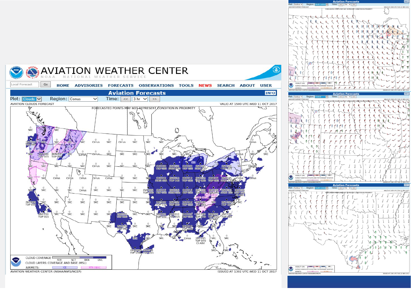
Fig. GFA 4. Three hour static images include overlaid AIRMETS ZULU (Icing), and
SIERRA (Mountain Obsecuration).
14 Graphical Forecasts for Aviation
Fig. GFA 4 illustrates the CONUS Aviation Clouds Forecast graphic. The graphic
contains Cloud Coverage (few/scattered, broken, overcast) grid, with Mean Sea Level
(MSL) overlay of BKN or OVC cloud bases and tops below FL180. LYRD represents top
of the highest multiple layers of BKN or OVC clouds; CI ABV indicates cirrus clouds
above. Graphical AIRMETS SIERRA (Mountain Obscuration), and ZULU (Icing) are
overlaid on the product. (See callout for eastern region selectable coverage.)
Advantages and Limitations
Advantages
• Displays for non-meteorologist users.
• A single source for multiple products.
• Temporal resolution 1 hour.
• Arial resolution (overlay) 1.2 nm (2.2 km).
• Forecasts to 15 hours.
• Available continuously.
• Updated continuously.
• Display scalable and customizable.
Limitations
• Surface/Clouds forecasts temporal resolution 3 hours.
• Weather Grids are point forecasts.
• No amendments. (Weather Advisories automatically amend the forecast.)
• Primarily low altitude products (below FL180).
• Automated; may not be as accurate as forecast with human involvement.
• Displays may suffer from clutter.
• Users may disable certain overlays, eliminating areas of hazardous weather.
15
For our purposes, the discussion only address weather—airspace classification in not
considered. Pilots must take into account personal minimums, the limitations of their
aircraft and its equipment, and their individual fitness for the planned flight (Risk
Evaluation and Management).
Although GFA temporal coverage is one hour, pilots should review conditions
at least two hours before and after proposed flight time—to determine trend.
When using the GFA, the display of too much data (clutter) on a single page
may obscure important information.
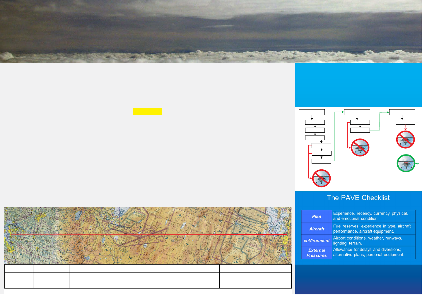
Refer to Fig. GFA A-1 and the callout—next page. With the exception of the coastal
hills, terrain through California’s Central Valley rises from sea level to about 500 ft.
Peaks through the Sierra Nevada mountains climb to about 11,500 ft, with passes in
the 8000 to 9000 foot range. The Great Basin of Nevada and Utah consist of valley
floors from 4000 to 6000 ft and maintain peaks between 9000 and 11,000 ft.
Caution
Fig. GFA A1-1. Consider a flight from Oakland, California to Salt Lake City, Utah.
Segment CSTL/VLY SIERNEV NV UT
Terrain
(100 ft)
SL-005 Peaks 115;
Passes 080-090
VLYs 040-060; Peaks 090-110 VLYs 040-050;
Peaks 090-110
Planning
Terrain
Altitudes
Environment
Weather
Minimums
Alternates
Aircraft
Performance
Equipment
Fitness
Pilot
Whether you use the “Risk” decision
tree (below) or the FAA’s “PAVE”
checklist, perform a systematic
evaluation for each ight—no matter
how simple or complex.
Appendix 1: Using the
Graphical Forecasts for Aviation
16 Appenndix 1: Using the GFA
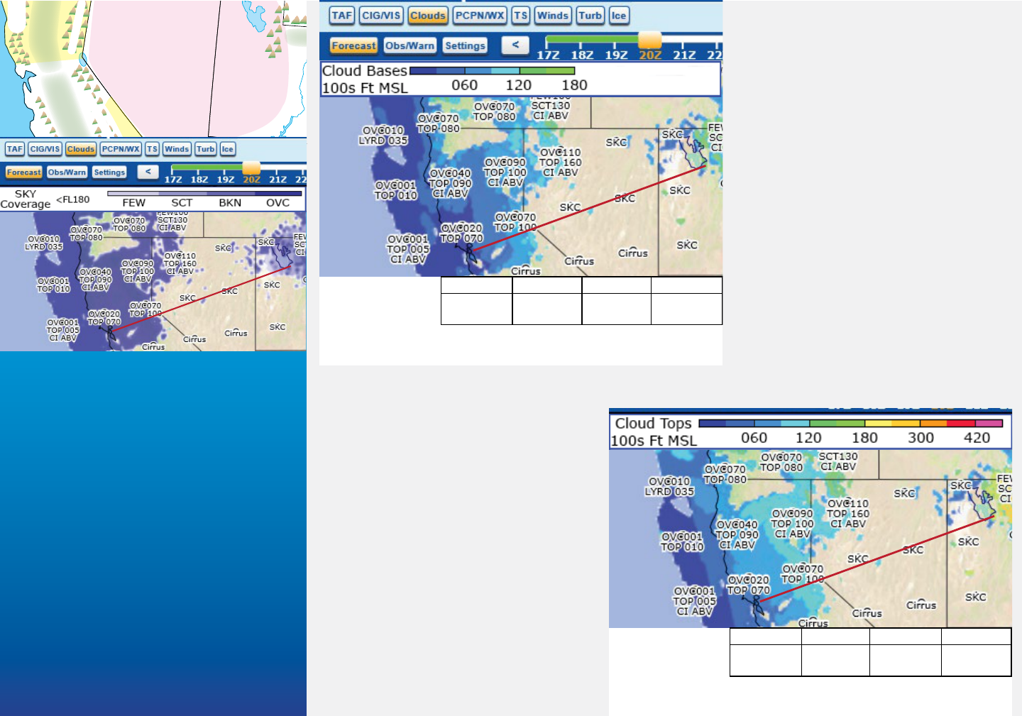
The following discussion is based
on the Weather Overlays and
Weather Grids (“Settings”). From
Fig. GFA A1-2 and the callout,
cloud cover and bases from the
coast through the Central Valley:
BKN-OVC030-060. The Sierra
Nevada range is the most chal-
lenging/highest risk part of the
flight. Mountain peaks and high-
er ridges are obscured in clouds
and precipitation—MTN OBSCN
AIRMET in effect which can be
displayed in “Settings.” Through
northern Nevada and Utah
higher mountain peaks may be
obscured; but, not enough areal
coverage to warrant an AIRMET.
Tops, for VFR as well as IFR oper-
ations, are important for aircraft/
equipment—airplane ceiling,
availability of oxygen, icing poten-
tial. Freezing and icing levels and
intensities (AIRMET Zulu) are
available on the Ice page. Based
on the Weather Overlay Fig. GFA
A1-3, through the Central Valley
tops are forecast to 9000 ft; across
the Sierra Nevada mountains
12,000 ft; and, into Utah 15,000
ft to FL180. Most of the higher
tops in Utah lie to the east of our
destination.
C
O
R
N
E
R
S
F
O
U
R
WHITE
MTNS
MTNS OF NRN
& NERN AZ
M
O
G
O
L
L
O
N
R
I
M
SRN
DESERTS
C
O
A
S
T
A
L
M
T
N
S
O
W
E
N
S
V
L
Y
T
E
H
A
C
H
A
P
I
M
T
N
S
COASTAL MTNS
SAN JOAQUIN VLY
SRN
CA
SRN SIERNEV
SACRAMENTO
VLY
CNTRL
CA
NRN
CA
S
H
A
S
T
A
S
I
S
K
I
Y
O
U
M
T
N
S
NRN SIERNEV
NE
CA
COASTAL
MTNS & VLYS
PACIFIC COASTAL WATERS
GREAT
BASIN
UNITA
MTNS
WASATCH MTNS
UNITA BASIN
LAKE
TAHOE
GREAT
SALT LAKE
LAKE
MEAD
LAKE
POWELL
GREEN R.
GILA R.
Fig. GFA A1-2. Heights on the Clouds page are
Mean Sea Level (MSL).
CSTL/VLY SIERNEV NV UT
BKN-OVC
030-060
BKN-OVC
090
SKC-FEW
090-120
SCT-BKN
090-120
Fig. GFA A1-3. When determining cloud tops,
always round up to the next highest value.
CSTL/VLY SIERNEV NV UT
TOPS090 TOPS120 TOPS150-
FL180
Appendix 1: Using the GFA 17
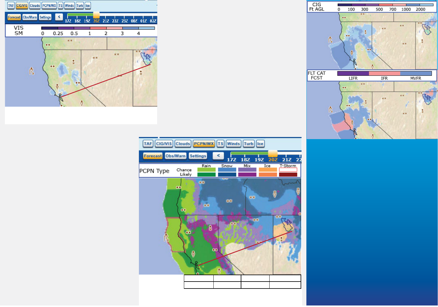
From Fig. GFA A1-4 surface visibilities
along most of the route are greater than
5 miles. The “FLT CAT” graphic (callout)
shows a small area of IFR in the San
Francisco Bay. This is NOT reflected in
either the “CIG” or “VIS” graphics; nor
in AIRMET SIERRA.
Note
GFA grid visibility and ceiling res-
olution exceeds AIRMET SIERRA
requirements. Localized conditions
may not be reflected in the product.
Fig. GFA A1-5 describes precipita-
tion and weather types. From the
coast through the Central Valley rain
showers (SHRA) are “Likely” (>50%
probability). Over the SIERNEV rain
and snow (RASN) probability re-
mains “Likely.” East of the SIERNEV
RASN probability decreases to
“Chance” (for our purposes trans-
lated as scattered—≤ 50% probabil-
ity). In NRN UT the GFA predicts
a “Chance” of freezing precipita-
tion—freezing drizzle or freezing rain
(FZDZ/FZRA).
On the precipitation and weather
types page thunderstorms are not ex-
pected to affect the route. (Scattered
thunderstorms are forecast for the
Fig. GFA A1-4. Like the text FA, only visi-
bilities less than 6 SM are forecast.
Fig. GFA A1-5. The Weather Grid depicts precipita-
tion coverage and. probability.
CSTL/VLY SIERNEV NV UT
SHRA RASN SCT SNRA RASN FZRA
Forecast, CIG/VIS Weather Grid
Ceiling resolution:
100 ft – 0-100
200 ft – 100-700
1000 ft – 1000-3000
Visibility resolution (statute miles):
1/4 ml – 0-1/4
1/2 ml – 1/2-1
1 ml – 1-5

18 Appenndix 1: Using the GFA
northern California coastal waters.) The
TS—Thunderstorm page (callout) confirms
the forecast and further defines coverage as
“Isolated.”
Based on Fig. GFA A1-6: From the coast
through the Central Valley winds are gen-
erally southerly, less than 20 knots. Winds
across the crest of the SIERNEV increase to
25 gusting to 35 knots. Through the Great
Basin of Nevada winds back to southwest-
erly 10 gusting to 15 knots, becoming light
and variable in Utah.
Refer to Fig. GFA A1-7 and the callout.
Terrain in western Tennessee rises from 300
ft to about 1000 ft in the eastern part of the state. In extreme eastern Tennessee into
Fig. GFA A1-6. GFA Winds provides more
detail than available with the Legacy text FA.
Fig. GFA A1-7. Consider a flight from Memphis, TN to Charlotte, NC.
C O A S T A L P L A I N
P I E D M O N T
C A P E
H AT T E RA S
A
T
L
A
N
T
I
C
C
O
A
S
T
A
L
W
A
T
E
R
S
G
U
L
F
C
O
A
S
T
A
L
W
A
T
E
R
S
PANHANDLE
E XTRM
N
N FL
C NTRL
S FL
E XTRM
S
KEYS
F lorid a
S trait s
L O W E R M I S S I S S I PP I VALLEY
APPALACHIAN
MOUNTAINS
Appendix 1: Using the GFA 19
western North Carolina mountain passes
are about 3000 ft, with peaks in the 5500
to 6500 foot range. Into the Piedmont
portion of the route terrain lowers from
1000 to 800 ft.
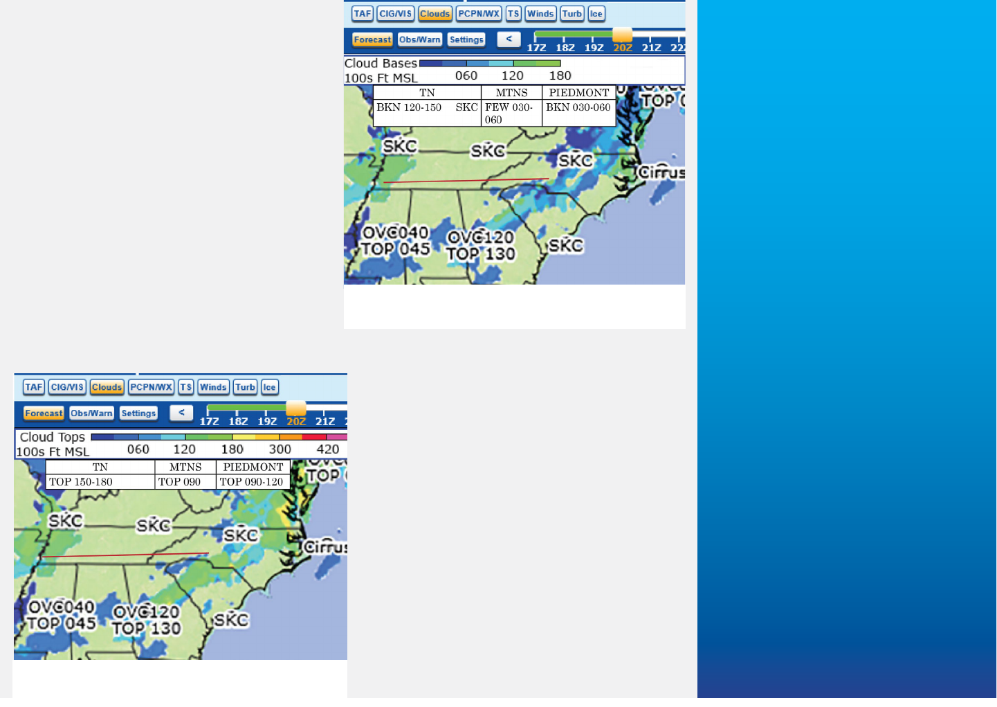
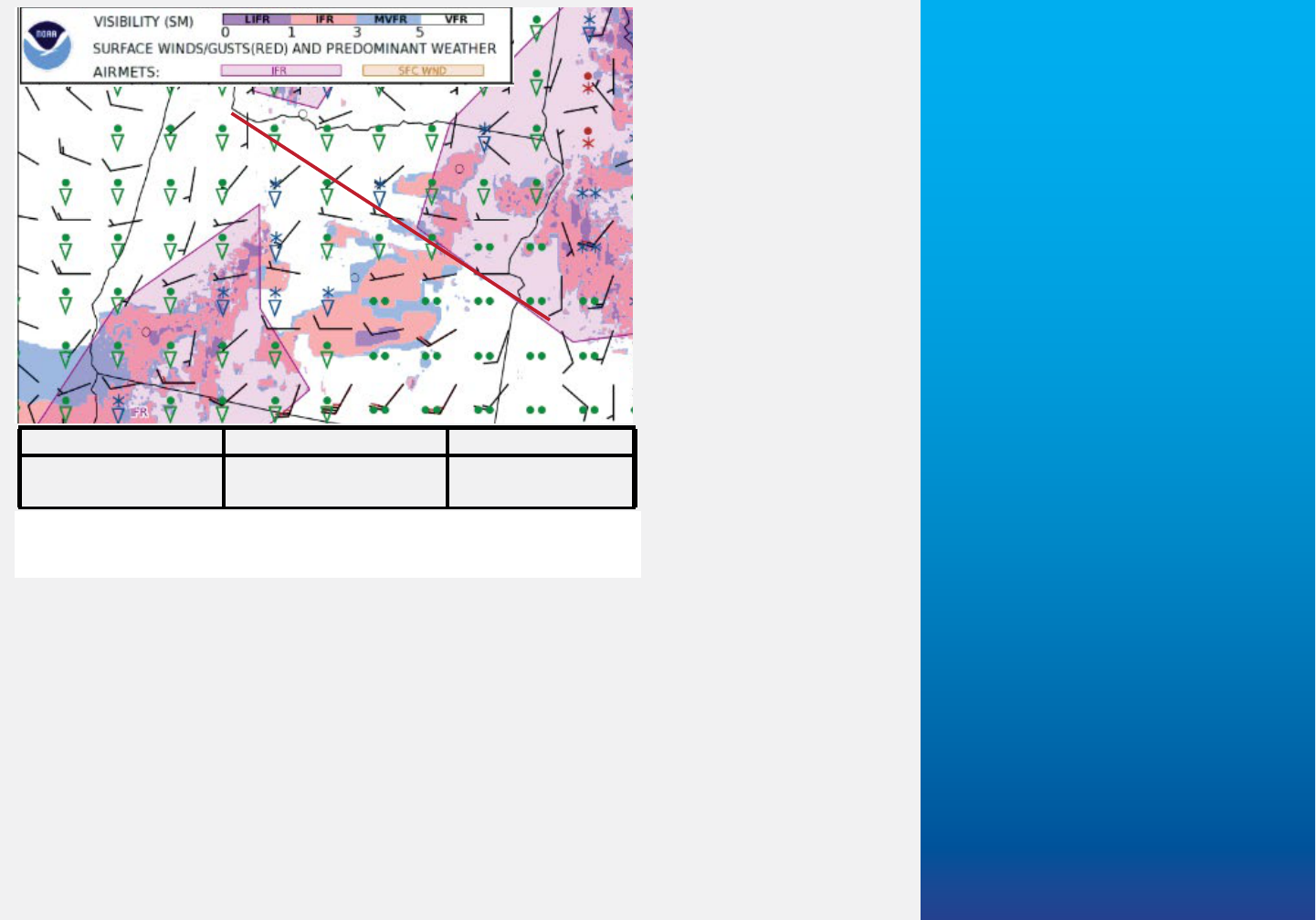
The following discussion is based on the
Weather Overlays and Weather Grids
(“Settings”). From Fig. GFA A1-8, cloud
cover and bases through Tennessee:
BKN-OVC120-150 becoming SKC in the
central and eastern portions. Over the
mountains of North Carolina: FEW030-
060; obscuring the peaks and possibly
closing some of the passes. Into the
Piedmont: BKN030-060; with most of
the coverage to the south and east of our
destination.
Recall the “Caution” in the previous
section: Weather Overlay symbology,
Winds barbs, and Clouds point forecasts
may NOT represent adjacent conditions.
Weather between points may be substan-
tially different, especially in mountainous
areas.
Based on the Weather Overlay Fig. GFA
A1-9, tops in western Tennessee are fore-
cast between 15,000 and 18,000 ft; across
the mountains 9000 ft; and, into the
Piedmont 9000 to 12,000 ft.
From Fig. GFA A1-10 surface visibili-
ties along most of the route are forecast
Fig. GFA A1-8. Heights on the Clouds page
are Mean Sea Level (MSL).
Fig. GFA A1-9. When determining cloud
tops, always round up.
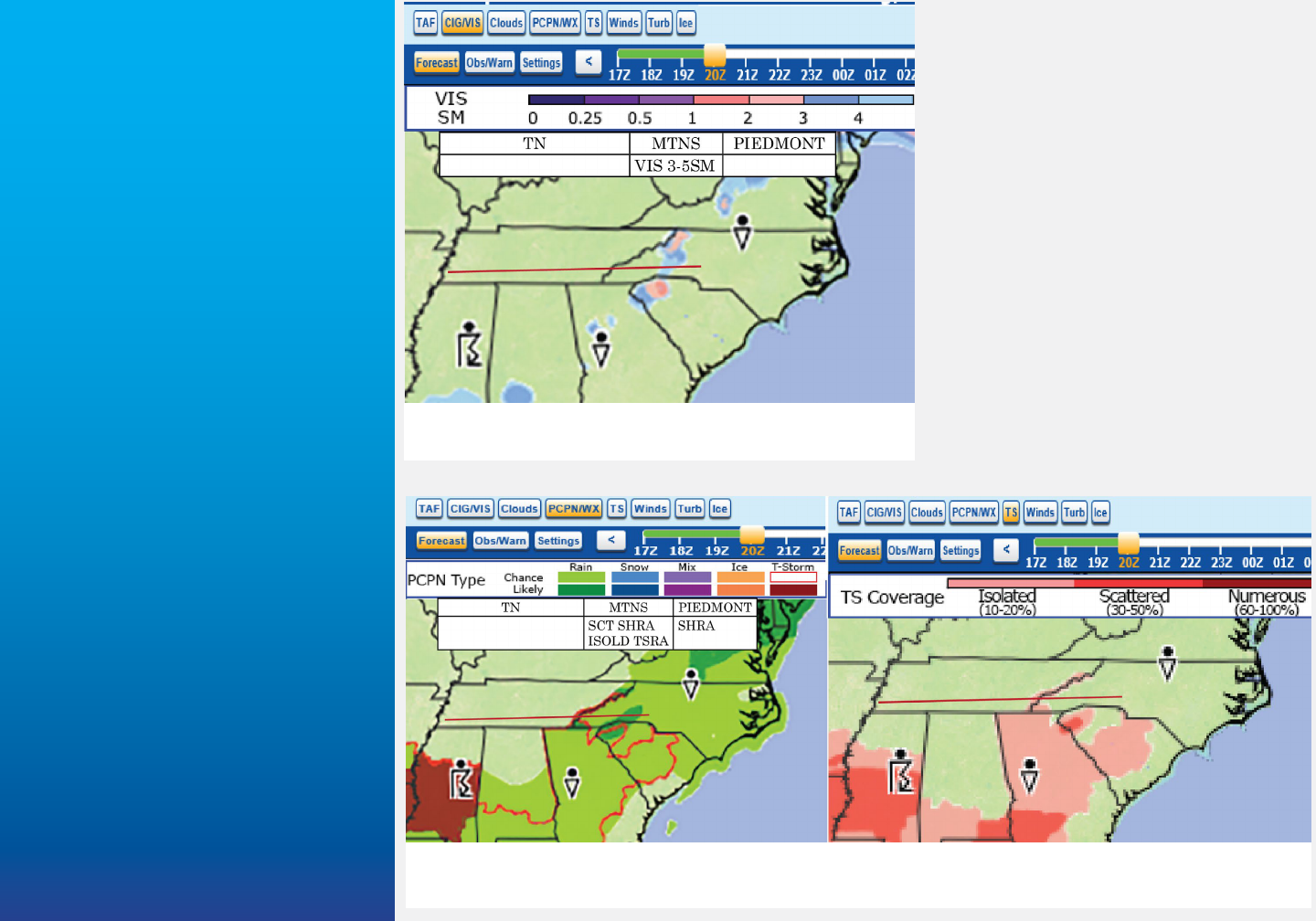
20 Appenndix 1: Using the GFA
greater than 5 miles. Visibilities
through the mountains and passes
3-5SM—an additional hazard to
VFR flight through the mountains.
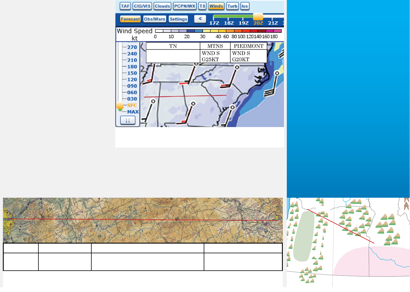
Fig. GFA A1-11 describes precipi-
tation and weather types. No sig-
nificant precipitation or weather is
expected for the Tennessee portion
of the route. Over the mountains
and into the Piedmont a “Chance”
(for our purposes translated as
scattered—≤ 50% probability) of
rain showers (SCT SHRA); possibly
“Likely” (>50% probability) in the
vicinity of any thunderstorm activi-
ty that develops. Into the Piedmont
SHRA are “Likely.”
Fig. GFA A1-10. Like the Lagecy text FA, only
visibilities less than 6 SM are forecast.
Fig. GFA A1-11. The Weather Grid (left) depicts precipitation coverage and. probability; the Thun-
derstorm page (right) adds arial coverage .
Appendix 1: Using the GFA 21
On the precipitation and weath-
er types page thunderstorms are
expected to be scattered within
a narrow line. From the TS—
Thunderstorm page thunder-
storm coverage is “Isolated.”
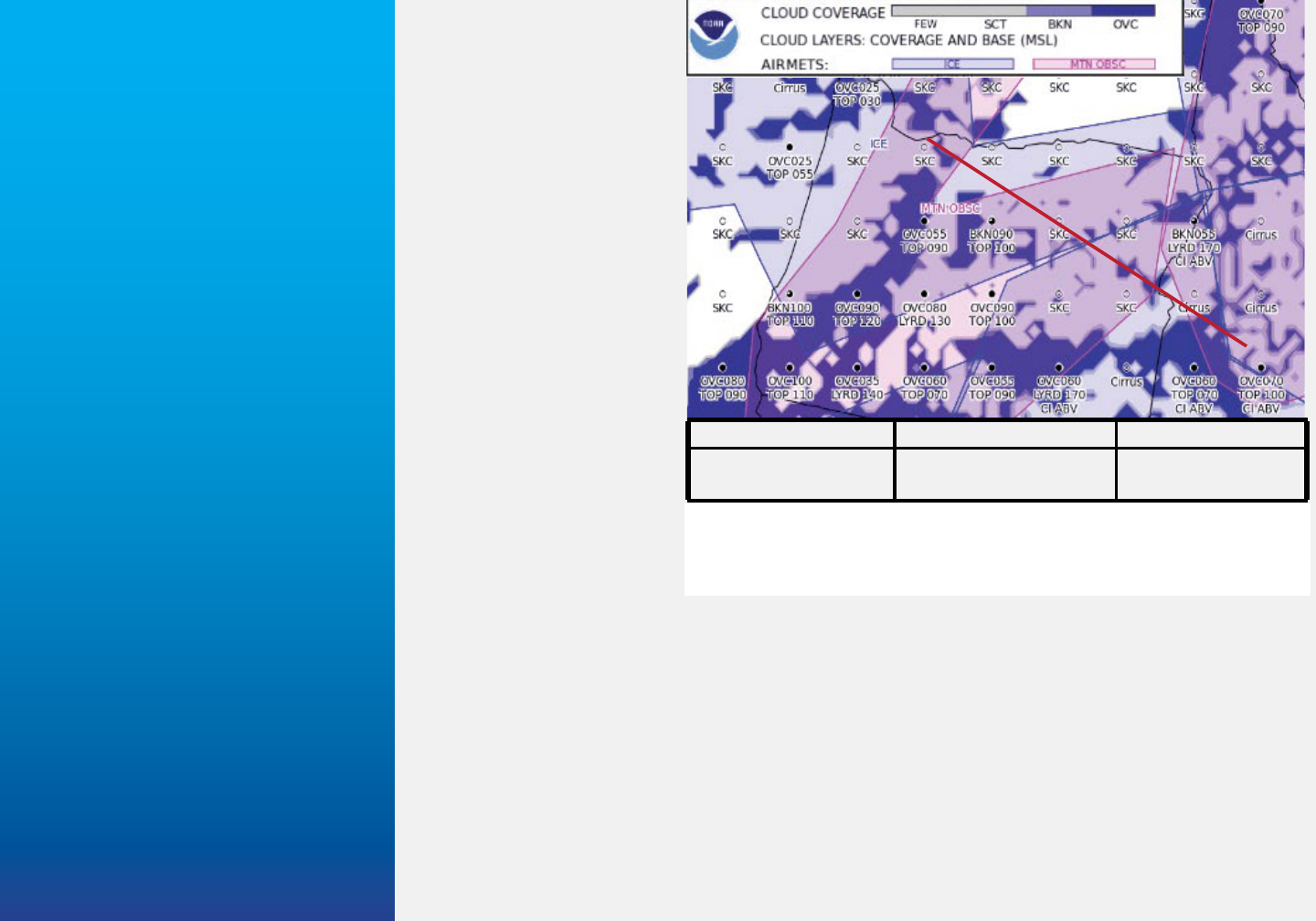
Based on Fig. GFA A1-12:
Surface winds throughout
Tennessee are forecast southerly
between 10 and 15 knots; over
the mountains winds increase to
25 knots —this analysis is based
on the Weather Grid (Legend
Fig. A1-12); and remain gusty
in the Piedmont at around 20
knots.
Aviation Surface Forecast and Cloud Forecast Graphics
Refer to Fig. GFA A1-13 and the callout. The Portland, Oregon area, located at the
north end of the Willamette Valley, has elevations less than 500 ft. Terrain rises
abruptly with the Cascade Mountains. Peaks rise to about 11,500 ft, with passes as low
Fig. GFA A1-12. GFA wind page provides more detail
than was available with the Legacy text FA.
CST/VLY CASCADES EAST OF CASCADES ID
SL-003 Peaks 115;
Passes 010-040
VLYs 020-040; Peaks 030-075 SNAKE RIVER VLY
030
Fig. GFA A1-13. Consider a flight from Portland, OR to Boise, ID; terrain heights are
(hundreds of feet) Mean Sea Level (MSL).
PACIFIC COASTAL WATERS
GREAT
BASIN
CONTINENTAL
DIVIDE
SWRN
MTNS
CNTRL
MTNS
PANHANDLE
MTNS
OF
NE OR
BLUE
MTNS
CASCADE
MOUNTAINS
COLUMBIA
R. GORGE
VANCOUVER IS.
PUGET
SOUND
COLUMBIA R.
SNAKE R.
COASTAL
MOUNTAINS
WILLAMETTE
VALLEY
SW
INTR
S
H
A
S
T
A
S
I
S
K
I
Y
O
U
M
T
N
S
S
N
A
K
E
R
I
V
E
R
V
A
L
L
E
Y
COLUMBIA
RIVER
BASIN
22 Appenndix 1: Using the GFA
as 1000 ft through the
Columbia River Gorge,
but generally in the 4000
foot range. East of the
Cascades valleys have
elevations from 2000 to
4000 ft and maintain
peaks between 3000
and 7500 ft—rising in
the eastern portion of
Oregon. The Idaho part
of the route consists of
the Snake River Valley
with elevations of about
3000 ft.
Fig. GFA A1-14 con-
tains an example of the
northwest region of the
Aviation Clouds Forecast
Graphic. Magenta shad-
ing represents AIRMET
SIERRA (Mountain
Obscuration), which includes the Cascades, mountains of eastern Oregon, and moun-
tains of Idaho. Fig. GFA A1-14 provides a “summary” of sky condition for the route, (All
heights are Mean Sea Level—MSL.) Forecast: West and over the Cascades SCT-BKN
025-055 TOPS100; Oregon east of the Cascades SCT090 TOPS100; Idaho OVC060
TOPS070-100.
Fig. GFA A1-15 represents an example of the northwest region of the Aviation Surface
Forecast Graphic. The magenta overlay designates AIRMET SIERRA (IFR). Aerial
coverage includes Washington, and northeast Oregon and Idaho north of the planned
route. “Summary” of visibilites and weather for the route: West and over the Cascades
VIS ≥5SM -SHRASN; East of the Cascades VIS ≥5SM OCNL 1-3SM –SHRASN—sur-
Refer to Table GFA A2-4 Conditional
Terms for additional coverage/
probability denitions.
W & O/CASCADES EAST OF CASCADES ID
SCT-BKN 025-055
TOPS100
SCT090 TOPS100 OVC060
TOPS070-100
Fig. GFA A1-14. Sky condition, in the Table at the bottom of
the illustration, is a “summary” for the route—similar to the
Legacy text Area Forecast.
Operationally, mountain obscuration
typically means VFR ight is possible
in the valleys, but may not be
possible through mountain passes
and particularly across mountain
ridges.
Appendix 1: Using the GFA 23
face winds variable less
than 10 knots; Idaho
VIS ≥5SM –RA WND S
10KT.
Based on the “Clouds”
and “Surface” forecasts
ONLY the weather does
not preclude VFR flight.
The most challenging
part of the route are the
mountains of eastern
Oregon. Even though
IFR AIRMET SIERRA
does not pertain to the
route, forecasts and
terrain indicate at least
local areas of IFR; most
likely due to precipita-
tion (RASN) possibly
obscuring higher moun-
tain peaks. However, the forecast indicates these areas should be circumnavigable.
Note
Operationally, expect AIRMET phenomena to affect over 50% of the area at
any time. Therefore, a pilot might encounter areas within the delineated por-
tion that are NOT affected by the hazard. This is not inconsistent, but reflects
the dynamic and transitory nature of weather. From a forecast perspective
phenomena usually lies well within the delineated area.
W & O/CASCADES EAST OF CASCADES ID
VIS ≥5SM
-SHRASN
VIS ≥5SM OCNL
1-3SM –SHRASN
VIS ≥5SM –RA
WND S 10KT
Fig. GFA A1-15. The Surface Graphic provides a composite
forecasts graphic of visibility, precipitation, and wind.
Weather-wise pilots determine
alternates—strategic ight planning.
A graphical product allows the visual
determination of an “escape route”
should the planned ight become
unsafe.
25
Appendix 2: Explanation/Definitions contains additional clarification and descriptions
of terms and symbols. (For further details refer to the information (INFO) pages of the
Graphical Forecasts for Aviation.
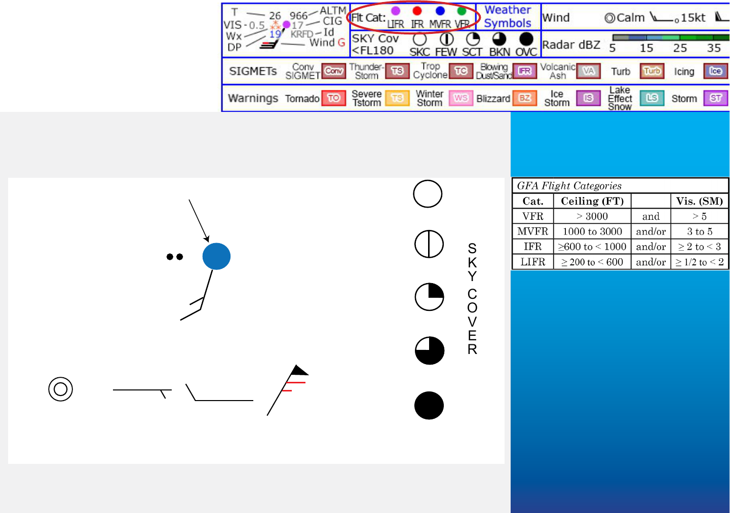
Fig. GFA-A2-1 displays “aviation interest” symbology used on GFA products. Flight
category definitions are contained in the callout; color codes in the Legend—shown in
the banner (red circle).
Sky Cover/
Flight Category
Temperature (ºF)
Altimeter
Ceiling
(LOCID)
Visibility/Weather 5
Dewpoint (ºF)
Wind
56
992
25
KLVK
48
SKC
FEW
SCT
BKN
OVC
...27010KT...
...09005KT...
...00000KT...
...03050G65KT...
WIND BARBs
“Red Wind” barbs indicate wind gusts.
Fig. GFA A2-1. Station Model Plot symbology used in the PRODUCT VIEW AREA.
Appendix 2:
Explanation/
Definitions
26 Appendix 2: Explanation/Definitions
Table GFA A2-1. GFA Warnings
NWS Warnings
Hazard Symbol Definition
Tornado
TO
Conditions favorable for the development of tornadoes.
Severe
Thunderstorms
TS
Conditions favorable for the development of severe thunder-
storms.
Winter Storm
WS
An advisory for a significant combination of hazardous winter
weather—snow, sleet, damaging ice accumulation.
Blizzard
BZ
Snow and/or blowing snow—visibility ≤ 1/4 mile; winds/gusts
≥ 30 knots.
Storm
ST
An advisory issued for sustained winds or gusts of 48 to 63
knots within.
Gale
GA
An advisory issued for sustained winds or gusts of 34 to 47
knots.
High Wind
HW
An advisory issued when sustained winds ≥ 34 knots or gusts
≥ 50 knots.
Ice Storm
IS
An ice storm event expected with an ice accumulation ≥ 1/2
inch.
Lake Effect
Snow
LS
Widespread or localized lake-induced snow squalls or heavy
showers.
International SIGMETs
Thunderstorms
TS
Widespread
1
thunderstorms; or, potential to significant effect
aircraft operations.
Tropical
Cyclone
TC
Organized convection over tropical or sub-tropical waters
with wind speeds > 34 knots.
IFR
IFR
Widespread
1
sandsorms/duststorms; or, a potential to signifi-
cant effect aircraft operations.
Volcanic Ash
VA
A volcanic eruption that produces volcanic ash emissions,
regardless of eruption magnitude.
1
Widespread—an area greater than 3000 sq. ml.
Small Craft Advisories for wind may
be added in the future.
Appendix 2: Explanation/Definitions 27
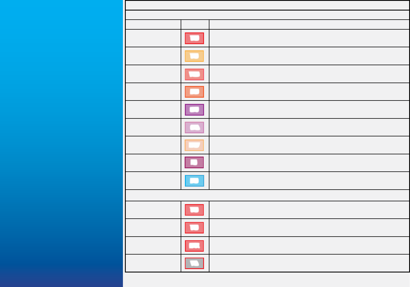
Table GFA A2-1. GFA Warnings provides contractions, symbols, and definitions used in
the PRODUCT VIEW AREA and LEGEND portions of the GFA page.
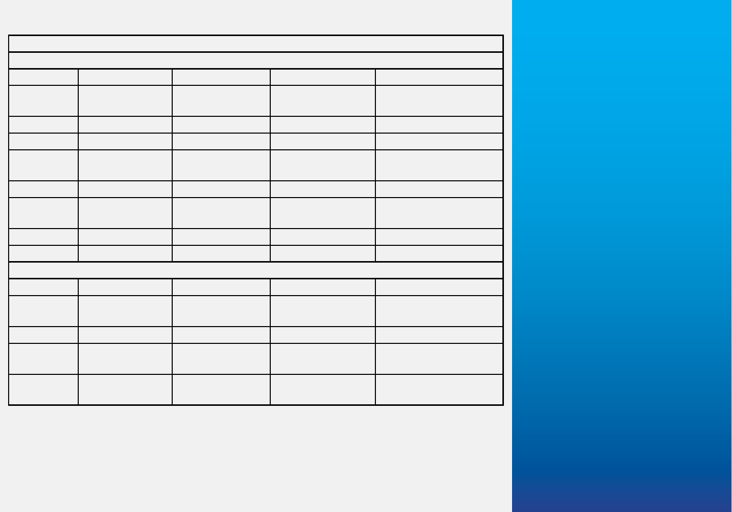
Table GFA A2-2. Hazards/Warnings used on the GFA Product shows those weather
advisories provided on individual Weather Products “Forecasts—Obs/Warn” Function
Button screens in the GFA PRODUCT VIEW AREA.
Table GFA A2-2. Hazards/Warnings
Forecasts—Function Button Products
Product AIRMET AWC SIGMET
1
Int’l SIGMET
2
NWS Warning
3
TAF Conv, Turb, Ice,
IFR
4
, VA
TS, TC, TB, IC,
IFR
4
, VA
TO, TS, WS, BZ, IS,
LS, ST, GA, HW
CIG/VIS Sierra (Cig/Vis) Conv, IFR
4
, VA TS, TC, IFR
4
, VA WS, BZ
Clouds Sierra (MtnOb) Conv, VA TS, TC, VA
PCPN/WX Conv, IFR
4
, VA TS, TC, IFR
4
, VA TO, TS, WS, BZ, IS,
LS, ST
TS Conv TS, TC TO, TS
Winds Tango (LLWS,
SFC Wind)
Conv TS, TC WS, BZ, IS, ST, GA,
HW
Turb Tango (Hi/Lo) Conv, Turb TS, TC. TB
Ice Zulu Conv, Ice TC, TS, IC @SFC WS, BZ, IS, LS
Obs-Warn (Observations and Warnings)—Function Button Products
Product AIRMET AWC SIGMET
1
Int’l SIGMET
2
NWS Warning
3
PCPN/WX Conv, IFR
4
, VA,
TS, TC, IFR
4
, VA
TO, TS, WS, BZ, IS,
LS, ST, GA, HW
CIG/VIS Conv, IFR
4
, VA, TS, TC, IFR
4
, VA WS, BZ
PIREP Conv, Turb, Ice,
IFR
4
, VA
TS, TC, TB, IC,
IFR
4
, VA
RAD/SAT Conv, Turb, Ice,
IFR
4
, VA
TS, TC, TB, IC,
IFR
4
, VA
TO, TS, WS, BZ, IS,
LS, ST, GA, HW
1
AWC SIGMET: Conv, Turb, Ice, IFR
4
, VA.
2
Int’l SIGMET: TS, TC, TB, IC, IFR
4
, VA.
3
NWS Warning: TO, TS, WS, BZ, ST, GA, HW, IS, LS.
4
IFR: Widespread DS/SS reducing VIS ˂3 ml.
28 Appendix 2: Explanation/Definitions
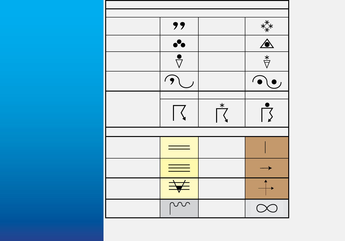
Table GFA A2-3.
Abridged GFA
Weather Symbols
contains symbols
most often used
on the Graphical
Forecasts for
Aviation. GFA
symbology de-
picts: precip-
itation type
and intensity,
probability, and
coverage; thun-
derstorm pre-
cipitation type,
probability and
coverage; and,
obstructions to
visibility.
The number of
symbols indi-
cates intensities
of drizzle, rain,
and snow: two
symbols light,
three symbols
moderate, four
symbols heavy.
Examples in
Table GFA A2-2:
drizzle light (-), rain moderate, snow heavy (+). Ice pellet intensity is not graphically
depicted. An elongated triangle depicts showers, with precipitation type. A horizontal
Table GFA A2-3. Abridged GFA Weather Symbols
Precipitation
-DZ (Drizzle)
+SN (Snow)
RA (Rain) (PL) Ice Pellets
-SHRA (Rain
Showers)
+SHSN (Snow
Showers)
-FZDZ (Freezing
Drizzle)
+FZRA (Freezing
Rain)
TS
(Thunderstorm)
TS TSSN +TSRA
Obscurations
BR (Mist)
BLDU/BLSA )
Blowing Dust/
Sand)
S
FG (Fog)
DS/SS (Dust-
storm/Sandstorm)
S
FZFG
(Freezing Fog)
BLSN (Blowing
Snow)
FU (Smoke)
VA (Volcanic Ash)
HZ (Haze)
On the GFA obstruction colors
denote areal coverage.
Appendix 2: Explanation/Definitions 29
line through the triangle indicates moderate or heavy intensity (snow showers exam-
ple). A “sign wave” symbol represents freezing precipitation, and type within the sym-
bol; one symbol light intensity, two symbols moderate or heavy.
A “lightning bolt” indicates thunderstorms, and precipitation type when accompanying
the thunderstorm. A double “lightning bolt” means heavy precipitation.
Note
For a complete list of symbols “Click” the Weather Symbols link in the
Legend—shown in the banner on the first page of this Appendix.
As shown in Fig. GFA
A2-2 Aviation Surface
Forecast Graphic excerpt
and legend, obstruction
symbol colors depict HZ,
FG, FU/VA, and DU/SA;
precipitation colors chance/
likely probability; and,
thunderstorm symbol color
coverage—ISO/SCT/NUM.
Since the early 1930s,
pilots have objected to
coded weather information.
When the FAA took over
most pilot weather briefing
responsibilities in the 1960s, FSS read and explained reports. During DUATs initial
implementation reports were, again, distributed in coded format. Subsequently, sys-
tems were modified to provide “plain language” translations. As part of the communica-
tions revolution weather data has become available through in-cockpit displays—using
coded data. With the GFA, station models and weather symbols are back. We’ve come
full circle.
Fig. A2-2. Aviation Surface Forecast Graphic colors
depict probability and coverage.
1
9
3
0
s
T
e
l
e
t
y
p
e
-
F
a
c
s
i
m
i
l
e
M
a
p
s
F
S
S
1
9
6
0
s
1
9
9
0
s
D
U
A
T
s
1
9
9
5
P
l
a
i
n
L
a
n
g
u
a
g
e
2
0
0
5
D
a
t
e
L
i
n
k
2
0
1
8
G
F
A
30 Appendix 2: Explanation/Definitions
Table GFA A2-3. Conditional Terms
provides areal coverage and prob-
ability of precipitation. Coverage/
Probability percentages are a sum-
mary based on computer generated
models.
Table GFA A2-4. Conditional Terms
Probability of Precipitation
Term Contraction Probability
Likely Lkly ≥ 55%
Definite DEF ˃ 50%
Chance CHC
25% - ˂55%
Slight Chance SChc
≤ 20%
Coverage
Term Contraction Coverage
Widespread Wide 80% - 100%
Frequent FRQ 75%
Numerous Num 60% - 70%
Patchy
1
Ptchy ˃ 50%
Scattered/Areas SCT/AREAS
30% - 50%
Widely Scattered WDLY SCT
≤ 20%
Isolated Iso
10%
1
Phenomena, such as Ground Fog, covering a
substantial area.
