Models:
2102, 2103, 2104,
2105, & 2106
"Manufactured in North America"
Applicable to Software Version 2.00-2.12
Owner's and Installer's Manual
for
Room Heating Units
For Customer Use
Please record your model and serial number below. This number is found on the identication
label located on the lower portion of the heater's left side panel. Retain this information for future
reference.
Model No. __________________________________________________________________________________
Serial No. ____________________________________________________________________
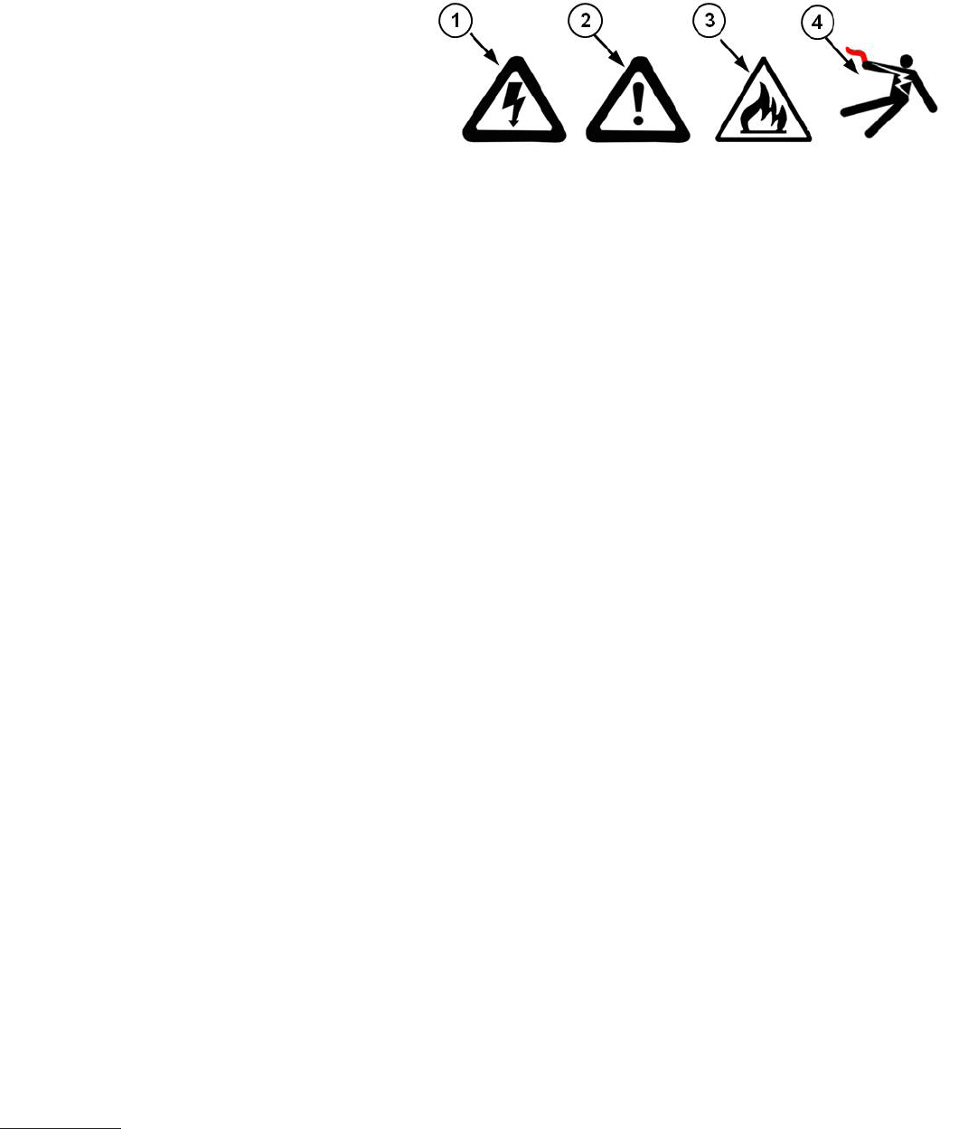
Safety Alert Symbols
Three safety alert symbols may be used to
alert you to personal safety instructions. They
are:
• Electrical (1 & 4)
• Mechanical (2)
• Fire (3)
These safety alert symbols are used to alert you to hazards. Obey all safety messages that follow
these symbols to avoid possible injury or death.
Signal Words
Signal words that may appear next to the safety alert symbol are:
• DANGER
• WARNING
• CAUTION
• IMPORTANT
• NOTE
Carefully read and understand the instructions before you continue.
DANGER indicates a hazardous situation which, if not avoided, will result in death or
serious injury.
WARNING indicates a hazardous situation which, if not avoided, could result in death
or serious injury.
CAUTION, used with the safety alert symbol, indicates a hazardous situation which, if
not avoided, could result in minor or moderate injury.
IMPORTANT indicates a special instruction or procedure which, if not followed, may
cause damage to the equipment.
NOTE indicates additional information about a subject or procedure for a more efcient or
convenient installation.
• The equipment described herein is intended for installation by a qualied technician
in compliance with applicable local, state, and national codes and regulations.
• To insure proper installation and operation of this product, completely read all
instructions prior to attempting to assemble, install, operate, maintain or repair
this product. Upon unpacking of the system, inspect all parts for damage prior to
installation and start-up.
• This manual should be retained by the owner upon completion of the installation and
made available to service personnel as required.
• Disclaimer: In compiling this manual, Stees has used its best judgement based upon
information available, but disclaims any responsibility or liability for any errors or
miscalculations contained herein, or any revisions hereof, or which result, in whole or
in part, from the use of this manual or any revisions hereof.
Personal Safety Instructions
Important
1. DO fully assemble the heater before energizing.
2. DOkeepallexplosivematerialsand/orammablegases
away from the room heating unit.
3. DO maintain the placement and clearance requirements.
4. DO keep items away from the discharge air grill area of the
heater.
5. DO disconnect power to all circuits before servicing. This
room heating unit may be connected to more than one
branch circuit.
6. DOcontactaqualiedservicetechnicianforinstallation
of and/or service to this heater to ensure it is installed
and/or serviced in accordance with information contained
herein and with national, state, and local codes and
requirements.
7. DOcontactaqualiedservicetechnicianifa"COREFAIL"
message is displayed on the heater’s control panel.
Safety Precautions
2100 Series Safety Information
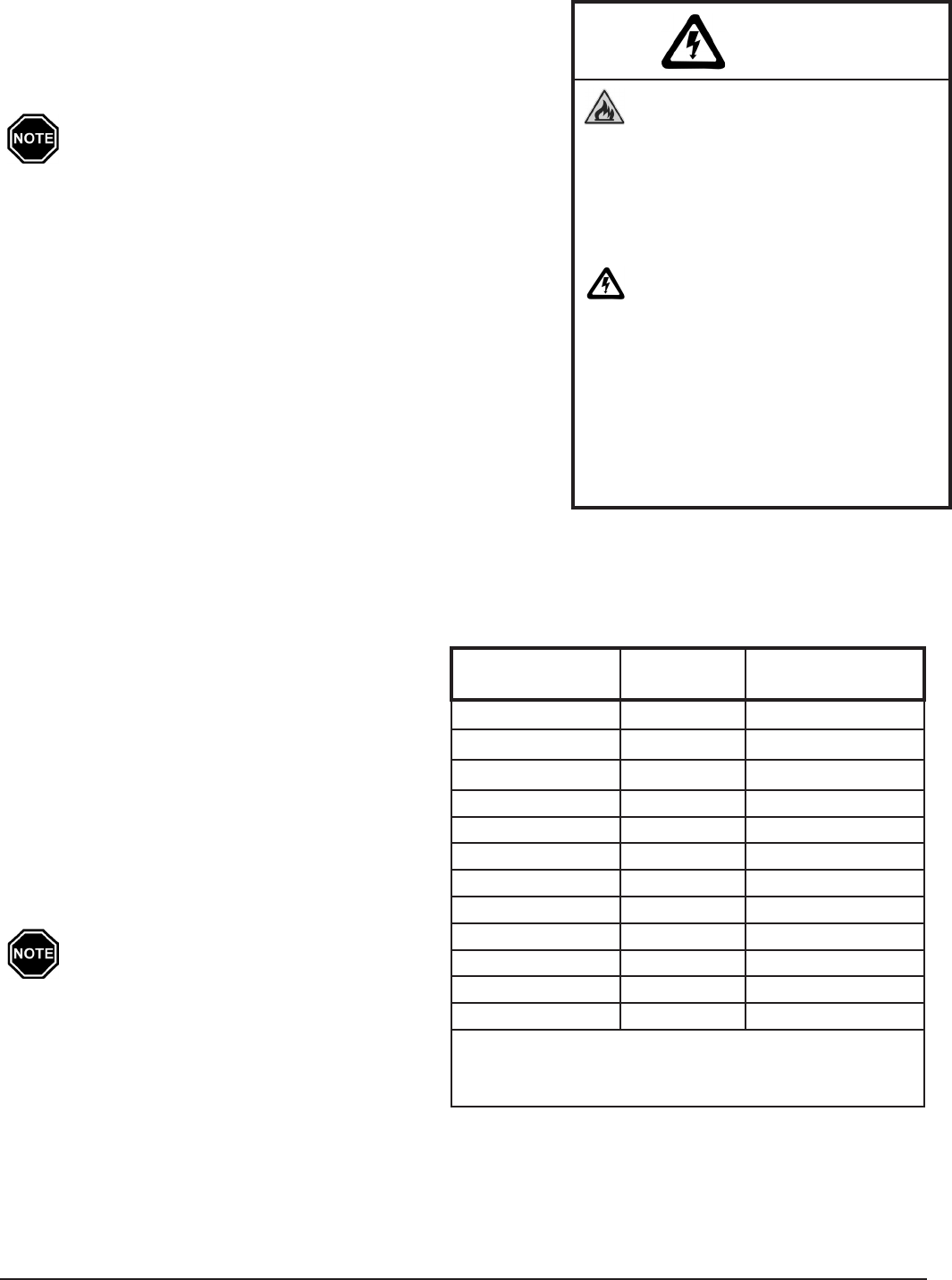
Built-in Safety Devices
WARNING
Hazardous Voltage: Risk of
electric shock. Can cause injury
or death. This heater may be
connected to more than one
branch circuit. Disconnect power
to all circuits before installing or
servicing. Installation of and/or
service to this equipment MUST
be performed by a qualied
technician.
Risk of re. Can cause injury or
death. Violation of the clearance
requirements can cause improper
operation of the equipment.
Maintain the placement and
clearance requirements specied.
DEVICE NAME FUNCTION LOCATION
ON HEATER
Core Charging High
LimitSwitch
(Manual Reset)
These limits monitor temperature along the back and top
panelsoftheheaterandthebrickcore.Ifnormaloperating
temperature is exceeded, one or both of these switches will
interrupt power to the heating elements and the heater's
controlpanelwilldisplay"COREFAIL".Ifthe"COREFAIL"
message occurs repeatedly, verify heater clearances have
not been violated and that objects have not fallen between
theheaterandthewall.Ifclearancesarecorrect,contacta
service technician.
InsidetheBackPanel
(Extends across the
length of the heater)
Clearance Violation
HighLimitSwitch
(Manual Reset)
InsidetheTopPanel
(Extendsacrossfront
edge)
DischargeAirHigh
LimitSwitch
(Manual Reset)
Monitors discharge air temperature and interrupts power
to the control circuit if normal operating temperature is
exceeded. This limit switch helps protect against the heating
of objects which may obstruct the air discharge area or
violategrillclearances.Ifnormaloperatingtemperatureis
exceeded, this switch will open . When this switch opens,
the discharge air system is disabled and the heater’s control
panel display will no longer illuminate. To reset the system,
pressthemanualresetbuttononthelimitswitch.Ifthe
switch opens repeatedly, verify that grill clearances are not
violated.Ifcorrect,contactaservicetechnician.
Insidethe
AirDischarge
Compartment
(Grill Area)
Tip Over Switch
(Heaters equipped with a
security base only.)
(Auto Reset)
Iftheheaterisnotintheuprightposition,thisswitch
interrupts power to the heating elements and the blower.
This prevents the heater from storing heat in or discharging
heat from the brick core.
InsidetheElectrical
Compartment
(Mounted on the Back Panel
to the Left of the Relay Board)
PowerIndicatorLight The power indicator light indicates that power is being
applied to the heater. Disconnect power to all circuits
before installing and/or servicing this equipment.
LowerRightCorner
(2100 Series Plug-In
Heaters Only)

Operation
General Operation ................................................................................................................................................. 1.01
ControlPanel ...........................................................................................................................................................1.01
RoomTemperatureControl ..................................................................................................................................1.02
Starting the System.................................................................................................................................................1.02
BrickCoreChargeControl .....................................................................................................................................1.02
AutomaticChargeControl ..............................................................................................................................1.02
Manual Charge Control ...................................................................................................................................1.02
Charge Control Override ........................................................................................................................................1.03
Maintenance and Cleaning .................................................................................................................................... 1.03
Installation
ShippingandPackaging ......................................................................................................................................... 2.01
Placement ................................................................................................................................................................ 2.02
ClearanceRequirements ........................................................................................................................................2.02
InitialSet-Up ............................................................................................................................................................2.03
Securing the Heater ................................................................................................................................................2.03
WallSupportBracket ....................................................................................................................................... 2.03
SecurityBase ....................................................................................................................................................2.03
LineVoltageElectricalConnections ......................................................................................................................2.04
DirectWiredRoomHeatingUnits ......................................................................................................... 2.04-2.05
CordConnected(Plug-In)RoomHeatingUnits ............................................................................................2.05
LowVoltageElectricalConnections-PeakControl ............................................................................................2.06
PowerLineCarrier(PLC)PeakControl ..........................................................................................................2.06
LowVoltageDirectWiredPeakControl ........................................................................................................2.07
TimeClockModulePeakControl ...................................................................................................................2.08
LineVoltagePeakControl ............................................................................................................................... 2.08
LowVoltageElectricalConnections-OutdoorTemperatureSensor(Optional) .............................................2.08
BrickLoading ........................................................................................................................................................... 2.09
CongurationMenu ...............................................................................................................................................2.10
Installer'sFinalCheck-OutProcedure ..................................................................................................................2.11
Appendix
Specications ...........................................................................................................................................................A.01
PartsDiagram .........................................................................................................................................................A.02
PartsList...................................................................................................................................................................A.03
InternalLineVoltageWiringDiagrams .................................................................................................................A.04
ManualResetLimitControls .................................................................................................................................A.05
InternalLowVoltageWiringDiagram ...................................................................................................................A.05
Help Menu ...............................................................................................................................................................A.06
ErrorCodes .....................................................................................................................................................A.06-A.07
HingingtheRightSidePanel .................................................................................................................................A.08
Glossary ...................................................................................................................................................................A.09
Warranty
Table of Contents 2100 Series
Table of Contents
TC
A
M
M
P
M
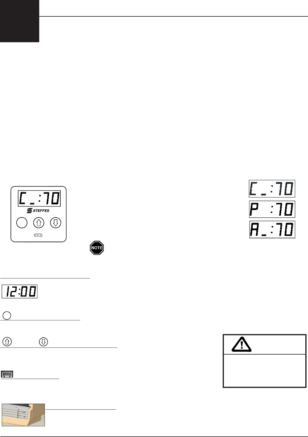
C = Chargeperiodoro-peaktime.
P = Peakperiodoron-peaktime.
A = Anticipatedpeakperiodorpre-peaktime.
(SpecialtyApplicationsOnly)
GENERAL OPERATION
SteesETSroomheatingunitsutilizeo-peakelectricityavailableduringthosetimesofthedayor
nightwhenthePowerCompanycansupplyelectricitymoreeconomically.Duringo-peakhours,
the room heating unit converts electricity to heat and stores the heat in its ceramic brick core. The
heater stores heat at varying levels depending upon outdoor temperature, owner preference, utility
peak conditions, and the requirements of the space being heated.
Asmallamountofheatisradiatedthroughtheheater’scabinet;however,mostoftheheatingis
accomplished by a thermostatically controlled blower. When the room temperature sensor senses a
temperature below the room temperature set point, the blower circulates room air through the brick
core. This air is heated and discharged back into the room to maintain a constant, comfortable room
temperature.
CONTROL PANEL
Alloperationalfunctionsoftheheaterarestoredinamicroprocessorandaccessedthroughthe
controlpanel.(SeeFigure1.)Generally,theuserwillonlyneedtousethispaneltoadjusttheroom
temperature.
ThefourdigitLEDdisplaysspecicoperatinginformation.Instandardoperation,thesedigits
continuously display current room temperature and one of the following brick core operating modes:
Operation
1
2100 Series Operation 1.01
Control Panel - Figure 1
A bar illuminates on the lower portion of the display's second
digit whenever the heating elements are energized.
AM and PM Indicator Lights
TheAMandPMindicatorlightsareonlyutilizediftheSteesTimeClockModuleis
being installed. With this module installed, the system displays time in 12 hour format
andthelightcorrespondingtoeitherAMorPMwillash.Thesystemcanbecongured
todisplaymilitarytime,inwhichcaseboththeAMandPMlightsilluminate.
Mode (EDIT) Button
Activatestheeditingmenuforchangingtheoperatinginformationoftheheater.
Up and Down Arrow Buttons
Increaseordecreaseroomtemperaturesetpoint.Alsousedtoscrollup
or down when viewing or changing the heater's operating functions.
Interface Port
FOR SERVICE USE ONLY! Allowstechnicianexternalaccessforupdating
software and troubleshooting.
Power Indicator Light
The power indicator light indicates that power is being applied to the heater. Discon-
nect power to all circuits before installing and/or servicing this equipment.
CAUTION
Editing operating
information may alter
the performance and
operation of the system.
P
M
M
A
P
M
M
A
P
M
M
A
M
P
A
M
M

ROOM TEMPERATURE CONTROL
The room temperature set point is adjusted by pressing the up arrow to increase or the down
arrow to decrease the set point. When the heater senses a heat call, the variable speed blower is
energized and circulates room air through the brick core. This heated air is discharged into the room
tomaintainthedesiredtemperature.Inaneorttokeeptheroomtemperatureconstant,theblower
automatically adjusts to the appropriate speed and may continue to operate after the set point has
been reached.
Iftheownerpreferstomonitorroomtemperatureatapointawayfromtheheater,anoptional
remoteroomtemperaturesensorisavailable.Aremoteroomsensoralsoprovidesmoreeven
heatdistributioninanareawheremorethanoneheaterisinstalled.Itisrecommendedtousethe
optionalremoteroomsensorinapplicationswheretherightsidepanelhaslessthana12"clearance
or where the right side of the heater is exposed to abnormal temperature conditions such as drafts
from a door or window.
STARTING THE SYSTEM
Onstart-up,odorsand/orsmallvolumesofsmokerelatingtorsttimeoperationoftheheating
components may occur. There also may be an odor associated with dust accumulation if the heater
isshutdownforanextendedperiodoftime.Allowtheheatertochargetoitshighestheatstorage
level(fullcorecharge)toexpeltheseodors.Referalsotomaintenanceandcleaningsectionofthis
manual.
Turningtheheater"OFF"suspendsallfunctionsoftheheater.Toturntheheater"OFF",usethe
downarrowtodecreasetheroomtemperaturesetpointuntil"OFF"isdisplayedonthefaceplate.
Toturntheheater"ON",usetheuparrowtoadjustroomtemperaturesetpointtothedesired
temperature.
The heater MUST remain "ON" if being used to supply a peak control signal to other
controlled loads.
BRICK CORE CHARGE CONTROL
The amount of heat stored in the heater’s brick core can be regulated by automatic or manual charge
control.Theheaterisfactorypresetforautomaticchargecontrolregulation.Ifmanualcharge
controlisdesired,theheatermustbereconguredatthetimeofinstallation.
AUTOMATIC CHARGE CONTROL
With automatic charge control, the brick core charge level is regulated automatically in relation
tooutdoortemperatureandtheheatingrequirements.AnoptionaloutdoorsensororStees
powerlinecarrier(PLC)systemisrequired.TheoutdoorsensororPLCsystemmonitorsoutdoor
temperature and provides this information to the heater. The heater responds by storing heat in the
brickcoreaccordingly.Nouserinterfaceisrequiredtoadjustthebrickcorechargelevel.
MANUAL CHARGE CONTROL
Ifmanualchargecontrolisbeingused,thebrickcorechargelevelmustberegulatedbytheuser.
During the heating season, the user needs to periodically adjust the brick core charge level setting in
relationtooutdoortemperatureandtheheatingrequirementsofthearea.Toconguretheheater
formanualchargecontrol,refertotheCongurationMenu(Page2.10).
Adjusting the Brick Core Charge Level (Manual Charge Control)
Step 1 PressandreleasetheM buttonuntil"CORE"isdisplayed.
Step 2 Presstheuporthedownarrowbuttontoadjustthebrickcorechargelevelsetpoint.The
charge level to be targeted can be set to any value from 0 to 100 percent.
Step 3 Once the desired charge level is set, press the M button once to return to normal display
mode.
Operation 1.02 2100 Series
2100 Series Operation 1.03
CHARGE CONTROL OVERRIDE
The heater is equipped with a charge control override feature that allows the user to force the heater
totargetafullcorechargelevel.Thisoverridecanbeinitiatedorcancelledatanytime.Ifanoverride
isinitiated,theheatertargetsafullcorechargelevelduringthenexto-peakperiod.Itcontinues
tochargeduringo-peakhoursuntiltheheaterachievesfull(maximum)corechargeoruntilthe
override is cancelled. Once full charge is achieved or the override is cancelled, the heater charges
accordingtoitsstandardconguration.
Initiate the Charge Control Override
Step 1 PressandholdtheM, the up arrow, and the down arrow buttons at the same time.
Step 2 Thefaceplatedisplaywillash“FULL”and“ON”.Continuetoholdallthreebuttonsuntil
“ON”displayscontinuouslyonthefaceplate.
Step 3 Releasethebuttons.Theoverrideisnowenabled.Thefaceplatewillreturntodisplayingits
standard operating mode.
Cancel the Charge Control Override
Step 1 PressandholdtheM, the up arrow, and the down arrow buttons at the same time.
Step 2 Thefaceplatedisplaywillash“FULL”and“OFF”.Continuetoholdallthreebuttonsuntil
“OFF”displayscontinuouslyonthefaceplate.
Step 3 Releasethebuttons.Theoverrideisnowcancelled.Thefaceplatewillreturntodisplaying
its standard operating mode.
MAINTENANCE AND CLEANING
Aswithmostheatingsystems,airborneparticlesandodorsin
the room may be drawn into the heating system and oxidized.
Since the room air passes directly through the hot brick core of
theETSheater,theoxidationprocesswillchangetheproperties
of these particles and odors. Odors can be amplied; thus, it is
recommended not to operate the heating system if odors such
as those from paints, varnishes, or chemicals are present in
the air.Allowtheareatobecompletelyairedoutbeforeoperating
the heater.
Asforairborneparticles,aftertheyhavebeenoxidizedtheyare
expelled back into the room and may accumulate on the heater or other surfaces. Over time, these
particles may appear as a black residue, commonly referred to as soot. High concentrations of air
borne particles from such things as aerosols, dust, candles, incense, pet hair, high humidity, smoke,
or cooking can contribute to poor indoor air quality and accelerate this process. To minimize the
blackresiduebuild-up,cleantheoutersurfaceoftheheateronaregularbasis.Washthecabinet,
only when cool, with a nonabrasive household cleaner. Do not use scouring powders or furniture
polish.Steesrecommendsusing"SoftScrubwithBleach"brandcleanseroranequal.
Regularlyvacuumaroundallsidesoftheheater.Checkthebackoftheheatertomakesureno
objects have fallen behind it and the grill area to make sure there isn't anything obstructing air
ow.Checkallsidesoftheheatertobesuretherequiredclearancesarenotbeingviolated.Objects
should never be placed on top of the heater.
Noadditionalroutinemaintenanceisrequired;however,havingaprofessionalservicetechnicianclean
the blower periodically will decrease the likelihood of undesirable blower noise due to dust accumulation.
No heater panel, with the exception of the painted front panel and painted right side panel, can
ever be removed from the heater. Should any other exterior panel(s) be removed, the heater must
be taken out of service permanently. All panels must be in place when operating the heater.
Risk of re. Can cause injury
or death. Violation of the
clearance requirements can
cause improper operation
of the equipment. Maintain
the placement and clearance
requirements specied.
WARNING
Installation
2
SHIPPING AND PACKAGING
The heater should always be transported in an upright
position to avoid damage to internal components and
insulation materials. The items shipped with each heater
include the following:
WALL SUPPORT BRACKET
(placed on shipping pallet un-
der heater...used in all heaters
except plug-in models)
SECURITY BASE
or
(packaged in heater
box on back side...
used only in plug-in
models)
Installation 2.01 2100 Series
(shipped inside the box on
top of heater )
CAUTION
Risk of personal injury. Steel
edges can cut. Use caution when
installing or servicing equipment.
3
or
BOXES OF CERAMIC BRICK
(shipped separately and
packaged 2 bricks per
package)
1
2102 8 pkgs
2103 12 pkgs
2104 16 pkgs
2105 20 pkgs
2106 24 pkgs
2102plug-in
MODEL
BRICK
INFORMATION PACKAGE
(includes Owner's Manual, Warranty
Registration Card, and Brick Installation Tool)
2
MOUNTING HARDWARE PACKAGE
(shipped inside heater's
electrical compartment...used in all
heaters except plug-in models)
4
SECURITY BASE KIT
(shipped inside heater's
electrical compartment...
used only in plug-in models)
8 pkgs
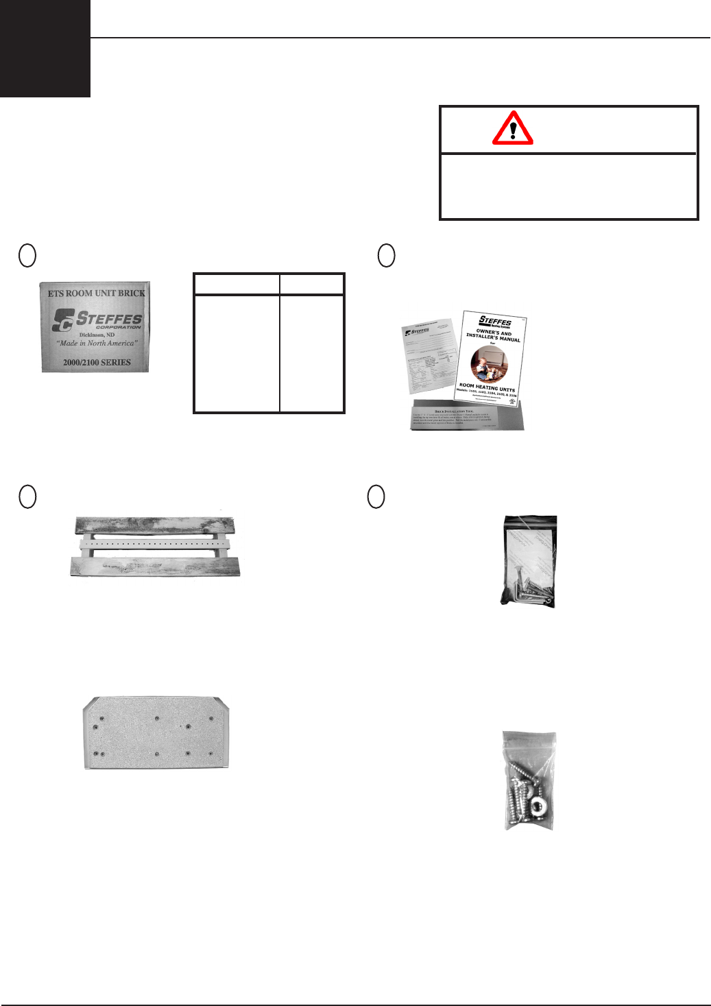
CLEARANCE REQUIREMENTS
There are minimum clearances that must be
maintained when choosing a location. (See
Figure2.)Theseareassurroundingtheheater
must be kept open and free of debris. Objects
such as curtains, furniture, or bed covers must
bekeptaminimumof4"fromallsurfacesofthe
heater. The back clearance is provided by the
wall mounting bracket or by the security base.
DONOTplaceobjectsofanykindontopofthe
heater.Theheatermayberecessedintoawall;
however, access to the heater's front panel and
grillMUSTNOTbeobstructedorenclosedandall
clearancerequirementsMUSTbemaintained.
2100 Series Installation 2.02
PLACEMENT
Theheatercanbeplacedonaninteriororanexteriorwall.Idealplacementisalonganinteriorwall,
adjacenttoanexteriorwall.Tondthebestlocationfortheheater,considerthefollowing:
• Physical Dimensions-AllclearancerequirementsspeciedintheClearanceRequirements
section(Page2.02)MUSTbefollowedtoensureproperoperation,safety,andperformanceofthe
equipment.
• Weight-TheweightoftheheaterMUSTbeconsideredwhenselectingalocation.Ifthereare
structural weight concerns, consult a building contractor or architect before installing.
• Flooring-Theheatercangenerallybeplacedonanystandardooring.Thebottomoftheheater
willbewarminnormaloperation;therefore,discolorationundertheheatermayoccurtocertain
ooringproducts.ContacttheooringmanufacturerorSteesCorporationwithquestions
regardingtheacceptabilityoftheoorcovering.Ifinstallingonextremelythickcarpet,itmaybe
necessary to slightly elevate the heater as carpet should remain at least ¾ inch away from air
discharge grill openings.
• Room Temperature Sensing -Toensureaccurateroomtemperaturesensing,avoidinstalling
theheaternearanopenstairwell,nearsourcesofheatorcold,orwithlessthan12"clearanceon
therightside.RefertoRoomTemperatureControlsection(Page1.02)forinformationregarding
the optional remote room temperature sensor.
Risk of re. Can cause injury or death.
Violation of the clearance requirements can cause
improper operation of the equipment. Maintain the
placement and clearance requirements specied.
WARNING
A clearance of 12" is recommended on the right side of heater. If there is less than a
12" clearance, a remote room temperature sensor is recommended to ensure accu-
rate room temperature sensing. The 12" clearance also allows space for hinging the
right side panel open for servicing.
Special requirements must be considered if placing the system in a garage or other
area where combustible vapors may be present. Consult local, state, and national
codes and regulations to ensure proper installation.
Minimum Clearances
Top 4"
Front&Grill 15"
Sides 2"
Back 11/2"
Minimum Clearances
Figure 2
1
1
2
"
15"
2"
4"
2"
(12" Recommended)

WARNING
Risk of re. Can cause injury or death. Failure to secure the heater can cause
the heater to fall over. Properly secure the heater by using the wall support
bracket to mount it to the wall or by installing the security base.
Installation 2.03 2100 Series
INITIAL SET-UP
Step 1 Unboxtheheaterandliftitotheshippingpallet.Placetheshippingboxasideuntilthe
brickloadingprocess(Page2.09).
Step 2 Placetheheaterinthedesiredlocationandcheckforproperclearancesonallsides.
Step 3 Removethescrewsattheloweredgeofthepaintedfrontpanel.
Step 4 Pulltheloweredgeofthepanelforwardandunhookitfromthetoppanel.Carefullyplace
the painted front panel aside to avoid damage.
No heater panel, with the exception of the painted front panel and painted right side panel, can
ever be removed from the heater. Should any other exterior panel(s) be removed, the heater must
be taken out of service permanently. All panels must be in place when operating the heater.
SECURING THE HEATER
The2100seriesroomheatingunitMUSTbesecuredforsafetypurposes.Adirectwiredheaterissecured
withawallsupportbracket,whileaplug-inheaterissecuredwithasecuritybase.
WALL SUPPORT BRACKET
Step 1 Removethemountinghardwarepackagefromits
shipping position inside the electrical compartment.
Step 2 Placethetopofthewallsupportbracket231/2"
fromtheoorandsecureittothewallwiththelag
boltsprovided.ThebracketMUSTbemountedso
thelagboltssecureintowoodwallstuds.Ifthewall
is not a standard wood studded structure, alternate
fasteners must be used.
Step 3 Attachthewallsupportclipstothebackofthe
heater.
Step 4 Set the carriage bolts aside as they will be used to
attach the heater to the wall support bracket after
theeldwiringconnectionsaremade.
SECURITY BASE
120Vplug-incordmodelscomeequippedwithasecuritybase.Thisbasemustbeattachedtothebottom
paneloftheroomheatingunit.Itispackagedinsidetheshippingboxonthebacksideoftheheater.
Step 1 Removethesecuritybasemountinghardwarepackagefromitsshippingpositioninsidethe
electrical compartment.
Step 2 Gentlylaytheheateronitsback.Foreaseofinstallation,slightlyelevatethebottomoftheheater.
Step 3 Aligntheholesinthesecuritybasewiththepre-drilledholesinthebottomoftheheater.
Usingthesix#14x1¼"sheetmetalscrewsandwashersprovidedinthemountinghardware
package, attach the security base to the painted bottom panel.
The angled corners of the security base will be towards the front of the heater
and the painted side of the security base faces up.
Step 4 Afterthebaseisattached,returntheheatertoitsuprightpositionandplaceindesired
location.DONOTenergizetheheateruntilinstallationiscomplete.
Wall Support Bracket Mounting
Figure 3
wall support
clip
attached to studs
lag bolts
23 1/2"
floor
carriage
bolt
wall support bracket

LINE VOLTAGE ELECTRICAL CONNECTIONS
Steesroomheatingunitsareavailableforconnectionto
variousinputvoltages.Standardcongurationfordirectwired
heatersis240V;cord-connectedheatersareconguredtoplug
intoa120Vwalloutlet.Todeterminethecongurationofthe
heater,refertotheUnitIdenticationLabelonthelowerleft
sidepanel.(SeeFigure4.)AllheatersareULandcULsafety
listed.
DIRECT WIRED ROOM HEATING UNITS
Instandardconguration,thechargingcircuitoftheheateriswiredforconnectionto240V/208V.
Ifconnectingto208V,theheaterwilloperateat75%ofitsratedwattage.Theblowerandcontrols
circuitintheheaterisconguredfor240V.Ifthecontrolcircuitistobeconnectedto120Vor208V,
contact the factory.
208V SYSTEMS ONLY:
Instandardconguration,Steesheatersaredualratedfor240Vand208Vpowerconnections.The
heatersarefactoryconguredfor240V.Ifthecontrolcircuitisoperatingon208Vpower,thevalue
inLocation16(L016)mustbechangedto210andthevalueinLocation28(L028)mustbechanged
toavalueof5forheatersequippedwithFascoblowerand10forP-Techblower.
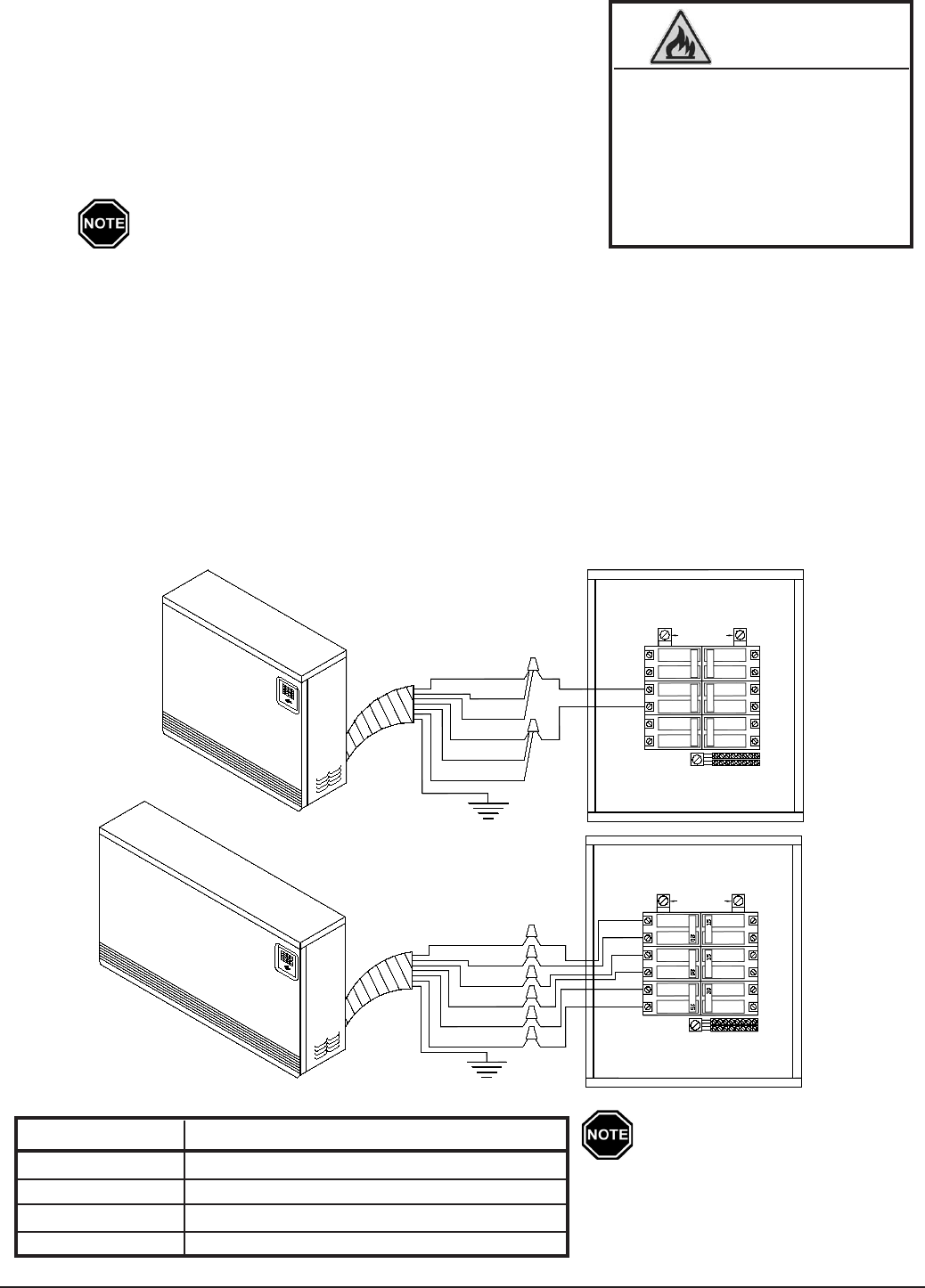
Field Connection Wire and Circuit Breaker Sizing Guide
All2100seriesheatersareequippedwithatwo-circuitelementfeedoptionandafan/controlcircuit
(Figure5onpage2.05).RefertotheUnitIdenticationLabelforpropersizingofeachcircuit.Ifsingle-
feedconnectionisused,sizethecircuitfortotalwattage.(ChargeCrct#1+ChargeCrct#2+Fan/Cntrl
Crct = Total Wattage.)
2100 Series Installation 2.04
Sample Unit Identication Label
Figure 4
HAZARDOUS VOLTAGE:
Risk of electric shock. Can
cause injury or death. DO
NOT energize the heater until
installation is complete. Equip-
ment must be installed by a
qualied technician in accor-
dance with applicable local,
state, and national codes and
regulations.
WARNING
Usecopperwireratedat75
o
C minimum only.
This eld connection wire and breaker size guide reects only the code interpretation
of Stees. It is the responsibility of the installer to comply with all applicable codes
and regulations.
Maximum kW
Wire Size 240 VAC 277 VAC 208 VAC
Maximum Curcuit
Breaker Size
#14AWG 2.8 3.3 2.4 15
#12AWG 3.8 4.4 3.3 20
#10AWG 5.7 6.6 4.9 30
#8AWG 7.6 8.8 6.6 40
#6AWG 11.5 13.2 9.9 60
Field Wiring
Step 1 Afterestablishingplacementoftheheater,mount
aeldconnectionjunctionboxinalocationwhere
heater-to-eldwiringconnectionscanbemadeeasily.
The junction box can be located beside the heater,
behindtheheater,ormountedintheoorbelowthe
heater.Steesrecommendsasteeljunctionboxto
provide protection against overheating.
The junction box MUST remain accessible for
future service to the heater and MUST be sized
in accordance with all applicable electrical
codes and regulations.
Step 2 Routethepropersizeandtypeofwiringfromthebreakerpaneltotheeldconnection
junction box.
Step 3 Connecttheeldwiringtothewiringharness(umbilicalcord)oftheheaterinsidethe
junction box.
Step 4 Removetheorangebreakerpanellabelfromthemountinghardwarepackage.Thislabel
MUSTbeappliedintheelectricalservice(breaker)panelandmarkedaccordinglytoidentify
the branch circuits feeding the room heating unit.
Installation 2.05 2100 Series
Typical System Wiring Diagram
Figure 5
Risk of injury or re. Poor
or marginal electrical
connections will cause the
connection to overheat and
fail. Use extreme caution
when making all electrical
connections.
WARNING
Wiring Harness (Umbilical Cord ) Color Code Chart
WIRE COLOR CIRCUIT DESCRIPTION
Black Circuitfeedfortwoofthefourheatingelements
Red Circuitfeedfortwoofthefourheatingelements
BlueandBlue/Black Circuitfeedfortheblowerandheater'scontrol
Green Ground
Connections shown are for
systems with a 240V/208V
blower/control circuit. Re-
fer to the Unit Identication
Label on the lower left side
panel of the heater for proper
voltage conguration.
RED
RED
BLACK
BLUE/BLACK
GREEN
3
15
30
6
BLACK
BLUE
CIRCUIT
SINGLE
CONNECTED
BREAKER PANEL
4
1
2
20
15
5
20
15
240VAC SOURCE
GREEN
MULTIPLE
CONNECTED
CIRCUIT
4
240VAC SOURCE
BREAKER PANEL
BLACK
BLUE/BLACK
BLUE
BLACK
RED
RED
2
3
1
6
5
CORD-CONNECTED (PLUG-IN) ROOM HEATING UNITS
All cord-connected heaters are factory-
conguredtobepluggedintoa120Vwall
outlet. The circuit outlet the heater is
plugged into should be designated solely to
the heater for circuit sizing purposes as well
as peak control and metering purposes in
some instances. To determine the correct
circuitsize,refertotheFieldConnection
WireandCircuit Breaker Sizing Guidein
this manual.
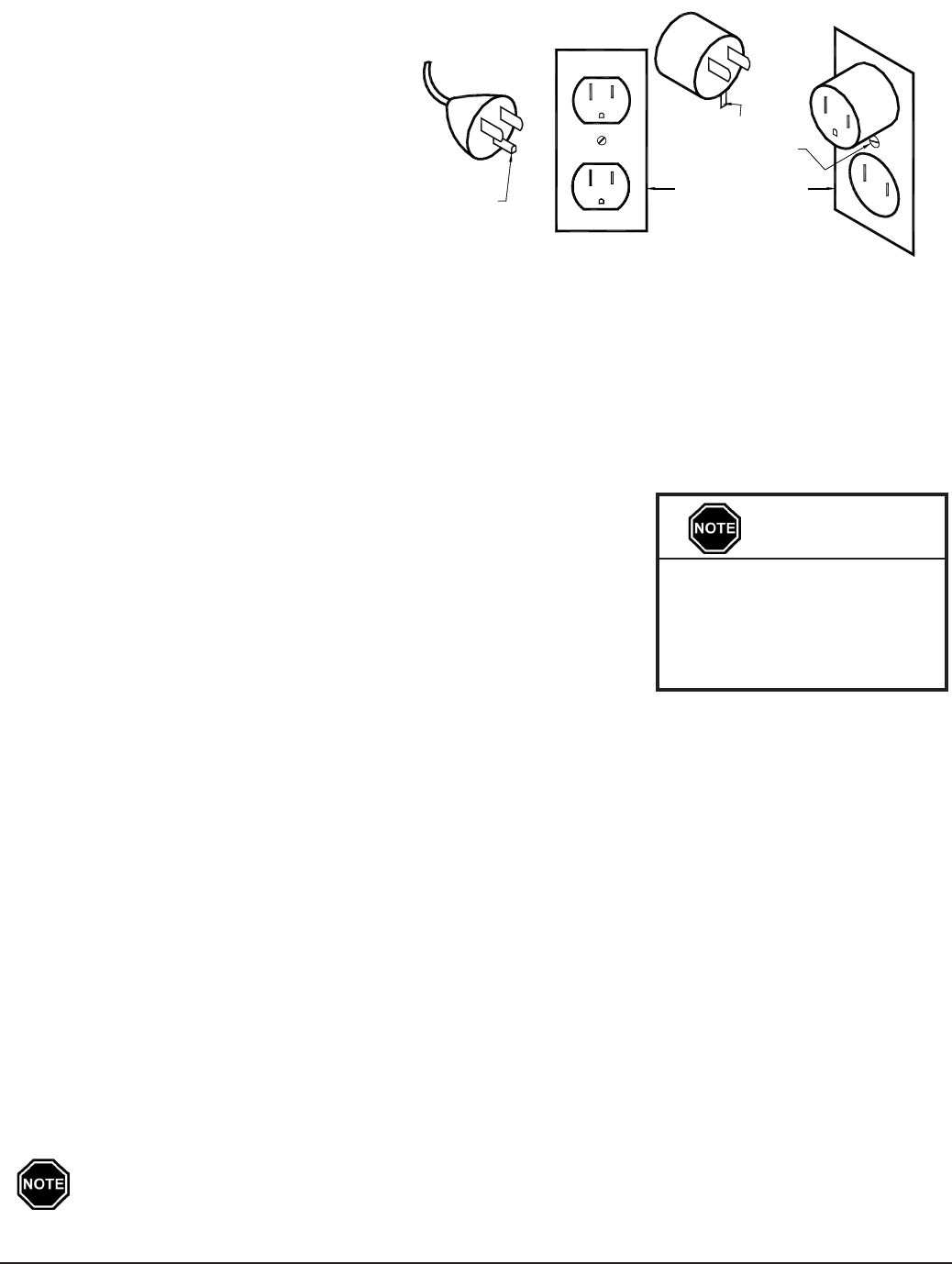
120Vcord-connectedroomheatingunits
must only be used with receptacles that are
of the grounding type and suitable for the
loadoftheheater.(SeeFigure6forcord
and receptacle requirements.)
Theroomheater'scordhasaplugasshowninFigure6A.Anadapter,asshowninFigure6B,isavailable
forconnectingthree-bladegroundingtypeplugstotwo-slotreceptacles.Thegreengroundingmeans
extending from the adaptor must be connected to a permanent ground, such as a properly grounded
outletboxasshowninFigure6C.Thisadaptorshouldnotbeusedifathree-slotgroundedreceptacle
is available.
PEAK CONTROL
SteesETSheatingequipmentisgenerallycontrolledbythePower
Company via a peak control signal. This signal can be sent to the
heaterusingtheSteesPowerLineCarriersystem,lowvoltagewiring,
aSteesTime Clock Module, orlinevoltage wiring. In applications
utilizing automatic charge control, outdoor temperature information
is required and can be received via an outdoor sensor or power line
carrier control.
The2100seriesroomheatingunitisfactoryconguredforusewithpowerlinecarriercontrol.Refer
totheCongurationMenu(Page2.10)forinformationonconguringtheheaterfortheapplication.
POWER LINE CARRIER (PLC) PEAK CONTROL
TheoptionalSteesPowerLineCarrier(PLC)controlsystemhastheabilitytocommunicatewiththe
heater through the existing electrical circuits in the structure. With the power line carrier option, hard
wired low voltage connections from the power company's peak signaling switch connect directly to the
transmitting device. The switch signals peak control times to the transmitter, the transmitter sends
the signal to an unlimited number of 2100 series heaters, which receive this information and respond
accordingly.
Inadditiontoprovidingpeakcontrolsignals,thetransmittingdevicealsoprovidesoutdoortemperature
information, room temperature set back, and anticipated peak utility control signals (if applicable).
AsthePLCsystemisoptional,itmustbespeciedatthetimeofordering.IfutilizingaPLCsystem,refer
totheOwner'sandInstaller'smanualaccompanyingthetransmittingdeviceforinformationonthe
installation and operation of the power line carrier control system.
PLC Communication is very reliable in most applications but can be aected and
hindered by connection method used, electrical layout of the application, operation
of other equipment in the same electric system, dirty power, etc. Stees does not
guarantee eective communication of the PLC system in all applications and is not
responsible for any communication issues outside normal operating malfunctions.
2100 Series Installation 2.06
Never install any wiring
in the line voltage
compartment of the 2100
series heater unless it is
rated for line voltage.
IMPORTANT
120V Receptable Requirements
Figure 6
Grounding Screw
Grounding Means
Grounding Pin
(Fig 6A)
3-Slot Grounded
Receptacle
Grounded Outlet
Box (Fig 6C)
Adapter (Fig 6B)
2-Slot Receptacle
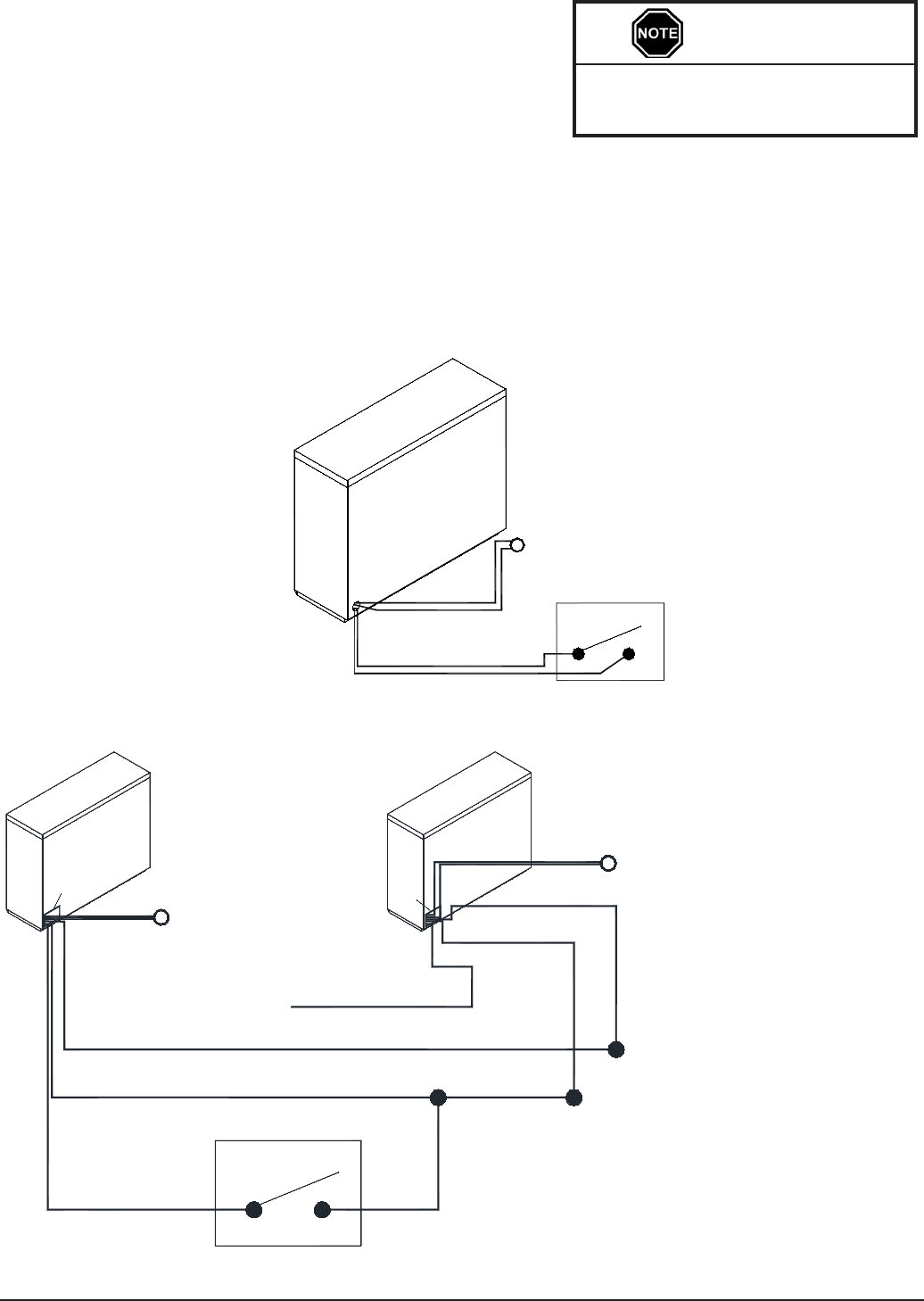
Multiple Unit - Low Voltage Connections Direct Wired Controls
Figure 8
Notes: 1. Connecting the low voltage hot (blue)
wire from multiple heaters to a single
control switch may cause damage to the
system. In multiple heater applications,
connect the wires as shown for proper
operation.
2. In this conguration, one outdoor sensor
is needed for each heater installed.
Installation 2.07 2100 Series
Single Unit - Low Voltage Connections Direct Wired Controls
Figure 7
LOW VOLTAGE DIRECT WIRED PEAK CONTROL
Ifusingthelowvoltagecontroloption,theheaterisdirect
wiredtothepowercompany'speakcontrolswitch.Field
connections from the switch are made to the heater’s low
voltage wiring harness through the low voltage raceway.
These wires are also accessible from inside the electrical
compartment.ClassII(lowvoltage)wiringshouldnever
enter a line voltage area of the heater, including its umbilical cord.
Somepowercompaniesalsouseanticipated(pre-peak)signals.Ifapplicabletoyourinstallation,
thecontrolswitchprovidingthepre-peaksignalcanalsobeconnecteddirectlytotheheaterwith
lowvoltagewire.RefertotheLowVoltageConnectionsDirectWiredControlsDiagram(Figure7)for
reference to peak and anticipated peak low voltage connections.
If routing low voltage wire near line
voltage conductors, shielded wiring
must be used.
IMPORTANT
Control Switch
Peak
Outdoor Sensor
Gray
Gray
Blue/White
Blue
BACK OF
HEATER
BACK OF HEATER
Blue/White (Peak)
Blue (Hot)
Black (Common)
Blue (Not Used)
BACK OF HEATER
Blue/White
Outdoor Sensor
Black
#2
#1
Gray
Gray
Gray
Gray
Peak Control Switch
Outdoor Sensor
(See Note 2)
(See Note 1)
(See Note 2)
Low Voltage
Junction Box
Low
Voltage
Junction
Box
TIME CLOCK MODULE PEAK CONTROL
TheSteestimeclockmodule(OrderItem#1301014)isanotheroption
for providing a peak control signal to the heaters. The optional time
clock module is installed inside the heater’s line voltage electrical
compartment and interfaces with the heater’s relay board. Peak
control times are required to be programmed into the heater once
the module is installed to enable the time clock feature.
Inadditiontoprovidingpeakcontrolsignals,thetimeclockmodule
can also provide automatic room temperature set back, if desired.
Refertotheinstructionsprovidedwiththetimeclockmoduleformore
information on the installation and operation of this device.
LINE VOLTAGE PEAK CONTROL
Linevoltagepeakcontrolisalsoanoption,butisnotthepreferredmethodasitisusuallymorecomplex
andexpensive.Iflinevoltagecontrolisutilized,theblower/controlcircuitoftheheatermustbepowered
withanuninterruptedcircuit.Anexternalswitchingdevice,suchasarelaypanel,isnecessarytodirectly
controltheheatingelementchargingcircuits.Ifrelyingonthismethodofcontrol,thefaceplateonthe
heatermustcontinuouslydisplayabrickcoreoperatingmodeof“C”(charge)regardlessofwhetheritis
ano-peakoron-peaktime.
LOW VOLTAGE ELECTRICAL CONNECTIONS - OUTDOOR TEMPERATURE SENSOR
(OPTIONAL)
The outdoor temperature sensor can be installed in one of two
ways:directwiredtothesystemorwiredtotheSteespower
linecarriersystem.Ifdirectwiredtotheheater,onesensor
perheaterisrequired.RefertotheLowVoltageConnection
Diagrams(Figures7and8)andtheinstructionsincludedwith
the sensor for information on the installation of this device.
Unless servicing, power
to the heater should not
be turned off at the circuit
breaker when using the
Steffes Time Clock Module.
If power is off to the blower/
control circuit for an
extended period of time, it
may be necessary to reset
the current day and time.
IMPORTANT
2100 Series Installation 2.08
Installation Methods: A) Hard wired to the heater
OR
B) ConnectedtoPowerLineCarrier(PLC)-referenceOwner'sandInstaller's
Manual for this installation.
Theory of Operation: The outdoor sensor monitors outdoor temperature and provides this informa-
tion to the system. The system responds by automatically storing heat in its
brick core according to outdoor temperature and the heating requirements.
Location of: The outdoor sensor must be placed in a location where it can accurately sense outdoor
temperatureandisnotaectedbydirectsunlightorotherabnormaltemperaturecondi-
tions.
Wiring to heater:
• Routelowvoltagewirefromtheoutdoorsensortotheelectricalcompartment
through one of the low voltage wire knockouts.
• Connect to the two gray wires in the low voltage raceway.
• Ifthesensorwiringisroutedthroughanexternalwall,theopeningthroughwhich
thewireisroutedMUSTbesealed.Failuretodosomayaecttheaccuracyofthe
outdoor temperature sensor.
• The outdoor sensor can be extended up to a total of 250 ft if needed.
• UnshieldedClassII(thermostat)wirecanbeusedasextensionwireaslongasitis
segregated from any line voltage cabling.
• Nootherloadscanbecontrolledorsuppliedthroughthiscable.Itisforconnection
oftheoutdoorsensorONLY.
• ThislowvoltagecableMUSTnotenteranylinevoltageenclosure.
If connecting to the Steffes power line
carrier (PLC) system, follow the instal-
lation instructions in the PLC system's
Owner's and Installer's Guide.
IMPORTANT
Installation 2.09 2100 Series
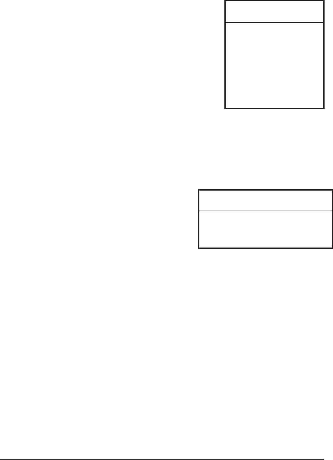
Figure 10
Note: Row 8 brick faces down
Row 7
Row 6
Row 5
Row 4
Row 3
Row 2
Row 1
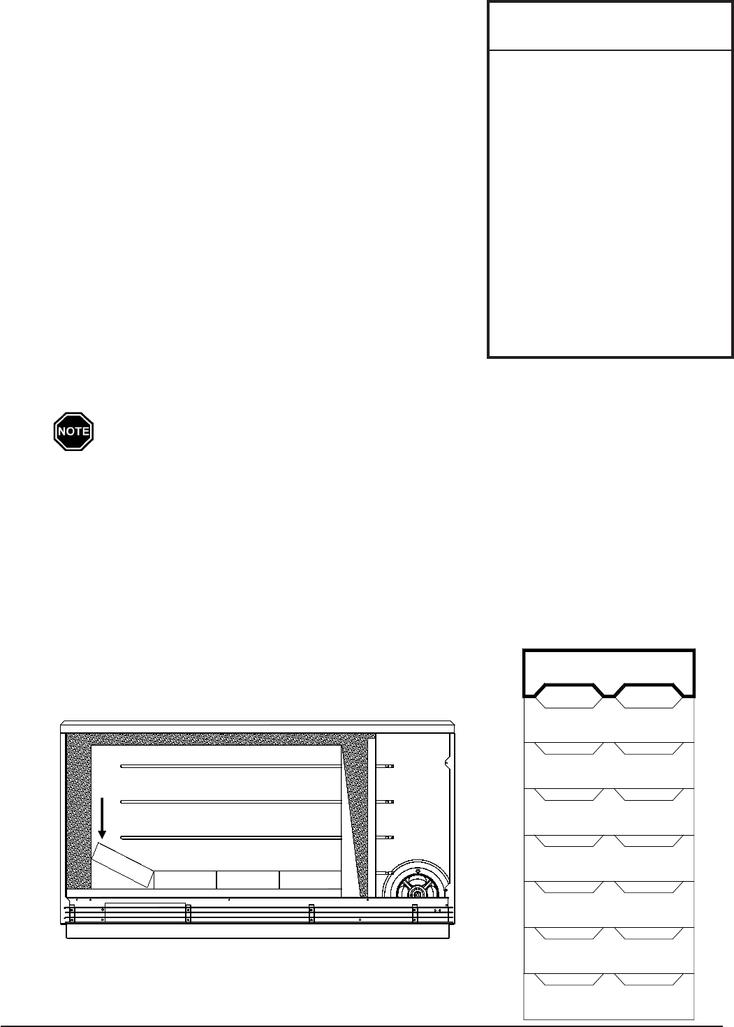
Brick Loading
BRICK LOADING
Step 1 Verify that the heater is not energized.
Step 2 Direct Wired Room Heating Units Only-Placetheheater
against the wall support bracket and use the carriage bolts
provided to securely mount the heater to the wall.
Step 3 Placetheshippingboxinfrontoftheheaterbeforeloading
thebricktocatchbrickdebris,toprotecttheooring,and
foreasyclean-upuponcompletionoftheinstallation.
Step 4 Removethescrewsontherightsideofthegalvanized
front panel and rotate the panel to the left to remove.
Step 5 IfinstallingaModel2104,2105,or2106,removeand
discard the cardboard spacer(s) from the brick core.
Step 6 Beginbrickloadingwithrowonebyinstallingtherstbrick
face-upandslidingtothefarrightsideoftheheater's
storagecavity.Besurethegroovedsideofthebrickisup
andtstightagainsttherightairchannelandtheback
insulationpanel.ContinueloadingthebricksforRow1
asshowninFigure9.Theinsulationontheleftsidemay
need to be compressed to install the last brick on each row.
To compress the side, squeeze the inner panel towards the outer panel as shown
in Figure 9 below.
Step 7 Continuethebrickloadingprocessonerowatatime.Allbricksinrowsonethroughseven
mustbeloadedwiththegroovedsideup.(SeeFigure10.)
Step 8 Installtheeighth(top)rowofbrickswiththegroovedsideofthebricksfacingdown.(See
Figure10.)A3"x11"metalbrickinstallationtoolisenclosedintheinformationpackageto
assistwithloadingthetoprowofbrick.Laythemetaltooloverthefarrightbrickinrow7.
Slideabrickoverthemetalpieceandintoposition.Pullthemetalpieceout.Continuethis
procedure until the entire top row of brick is installed.
Step 9 Once all bricks are loaded, replace the galvanized front panel.
Brick Placement
Figure 9
The heater MUST be securely
mounted to the wall or to its
security base prior to brick
loading.
To properly seal the brick
core, make sure all bricks are
installed correctly.
Install bricks carefully to
avoid damage to the bottom
and back insulation panels of
the storage cavity.
Maintain an even horizontal
line across the brick core
during brick installation so
air ow through the heater
is not obstructed.
IMPORTANT
4
3 2 1

CONFIGURATION MENU
Stees2100SeriesroomheatingunitshaveaCongurationMenu
which allows them to be customized to the power company and
consumer’sneeds.Thismenucanbeaccessedonstart-upandallows
congurationsettingstobeadjusted.
Accessing the Conguration Menu
Step 1 Energizeheater.AccesstoCongurationMenuisallowed
forrsttwo(2)minutes of operation. Ifheaterhasbeen
energizedforovertwo(2)minutes,itmustbepoweredoandbackonagain.
Step 2 PressandreleasetheMbuttonuntilthefaceplatedisplays“CONF”.
Step 3 Presstheuparrowonceandthefaceplatewilldisplay“C000”.Thedisplaywillashbetween
“C000”andthecorrespondingcongurationvalue.
Step 4 Ifnecessary,editthecongurationbypressingandholdingtheM button while using the up
or the down arrow button to change the value.
Step 5 Once the value is correct, release the buttons and press the up arrow button to go to the next
conguration(C001,C002,etc.).
Step 6 Repeatsteps4through5untilallcongurationsettingshavebeenadjustedtothedesired
values.
Step 7 Oncecongured,usethedownarrowtoleavetheCongurationMenu.
Inmostapplicationsonlyafew,ifany,congurationchangeswillbenecessary.Followingis
adescriptionofthecongurationsettingsandtheirfunctions:
C000 O-Peak Method of Charge Control -Setsthemethodofbrickcorechargingtobeused
duringo-peak(charge)periods.Heaterisconguredforautomaticchargecontrol,whichis
avalueofve(5).Toutilizemanualchargecontrol,changethevaluetosix(6).
C001 Start Brick Core Charge Set Point-IfutilizingautomaticchargecontrolassetinC000,this
value indicates the outdoor temperature at which the heater will start charging.
C002 Full Brick Core Charge Set Point -IfutilizingautomaticchargecontrolassetinC000,this
value indicates the outdoor temperature at which the heater will target a full core charge.
C003 Power Line Carrier (PLC) Channel Selection-IfusingPLCcommunication,thissettingmust
matchthechannelsettingintheSteesPLCtransmittingdevice.Avalueofzeroindicates
power line carrier communication is disabled.
C004 Optional Controls Conguration
Value Conguration Description
154 NoTimeClockModule/UtilizingPLCorManualChargeControl
155 NoTimeClockModule/DirectWiredOutdoorSensor
158 Time Clock Module/Manual Charge Control
159 Time Clock Module/Direct Wired Outdoor Sensor
C005 Control Switch Conguration-Ifutilizingpowerlinecarriercontrol,theSteestimeclock
moduleorlinevoltagecontrol,thisvalueshouldbezero.Forallotherapplications,thisvalue
should be one (1).
C006 ThiscongurationMUSTbesettoavalueofsix(6)forall2100Seriesroomheatingunits.
C007 Charge Factor-Thiscongurationshouldbesettoavalueofthirty(30).
C008-C012 Currently not utilized in 2100 Series room heating units.
C013-C021 Time Clock Module Conguration-Thesecongurationsettingsareusedtocongure
thepeakcontroltimeswhenutilizingtheoptionalSteesTimeClockModule.Refertothe
installationandcongurationinstructionsincludedwiththemoduleformoreinformation.
If access to Conguration
Menu times out, the system
must be powered o at the
circuit breaker and back on
to re-enter the menu.
IMPORTANT
2100 Series Installation 2.10
Installation 2.11 2100 Series
INSTALLER'S FINAL CHECK-OUT PROCEDURE
Withtheheaterde-energized,hingetherightsidepanel
open(PageA.08).Completethesystemcheck-outbelow:
Step 1 Inspectalleldconnectionstoensuretheyaretight
and that all wires are routed correctly.
Class II (low voltage) wiring or any wiring not
rated for line voltage should never be installed
in a line voltage area.
Step 2 Check the damper system to ensure the damper
operates freely and that there is no debris in this
area, which could inhibit its operation. To do so,
slowly press the damper lever extending from the
damperdownward.Becarefulnottobendthe
damperactuator.Ifthedamperisnotfree,remove
the blower and clean any debris from the damper.
Step 3 Make sure the blower operates by adjusting room
temperature set point above the actual room
temperature.
Step 4 Withthesysteminano-peak(charge)mode,
initiatethechargecontroloverride(Page1.03).
Step 5 Check for proper amperage draw on the charging
circuit(s).UsetheChargeCircuitAmperageDraw
Chartforreferencetothecorrectamperageofthespecicheaterbeinginstalled.
Step 6 Verify that the heater receives and responds to the utility peak control device and that all
other system controls are operating properly.
Step 7 Placegrillslatsinposition,ifremoved.
Grill slats should bow up to direct
airowup,awayfromtheoor.
Step 8 Placetherightsidepanelbackinto
position and secure.
Step 9 Returnthecontrolcircuitboardtoits
original position and install the painted
front panel.
Step 10Verifythatcongurationsettingsare
correctfortheapplication.Refertothe
CongurationMenu(Page2.10).
On start-up, odors and/or small
volumes of smoke relating to
rst time operation of the heating
components may occur.
Step 11 Make certain all fuses and/or circuit
breakers are labeled in the distribution
service panel as this system may be
connected to more than one branch
circuit.
Step 12Presentownerwiththemanualandwarrantyinformation.The owner's registration card
must be completed and returned to Stees Corporation to ensure warranty coverage.
The owner should retain the top portion of the card for their records.
WARNING
Risk of re. Can cause injury
or death. ETS devices run
for long periods of time at
high electrical loads. Poor or
marginal connections will cause
the connections to overheat and
fail.
Risk of electric shock. Can cause
injury or death. This heater may
be connected to more than
one branch circuit. Disconnect
power to all circuits before
installing or servicing. DO NOT
remove the painted front panel
while energized. Equipment
must be serviced by a qualied
technician.
CHARGE CIRCUIT AMPERAGE DRAW CHART
Input Wattage Woltage AMP Draw
1.32 kW 120 11.00
2.4 kW 240 10.00
3.0 kW 240 12.50
3.6 kW 240 15.00
4.5 kW 240 18.75
4.8 kW 240 20.00
5.4 kW 240 22.50
6.0 kW 240 25.00
7.2 kW 240 30.00
7.5 kW 240 31.25
9.0 kW 240 37.50
10.8 kW 240 45.00
(AMP draw is calculated by taking the total input wattage
divided by the input voltage. Allow +/- 5% tolerance at
nominal input voltage.)

Appendix
A
SPECIFICATIONS
* Refer to the Unit Identication Label on lower left side panel for data specic to your heater. In
standard conguration, the heater can be connected to 208V or 240V. Rated input at 208V is
75% of rated 240V input. If full rated input is required in 208V applications, contact the factory.
2100 Series Appendix A.01
Model 2102
plug-in
2102 2103 2104 2105 2106
Length-inches 30 30 37 44 51 58
Heights-inches 24.5 24.5 24.5 24.5 24.5 24.5
Depth-inches
(w/out wall bracket)
(w/wall bracket)
10.5
12
10.5
12
10.5
12
10.5
12
10.5
12
10.5
12
NumberofBricks 16 16 24 32 40 48
NumberofBrickPkgs. 8 8 12 16 20 24
WeightofHeater-lbs 105 91 112 126 145 164
WeightofBricks-lbs 176 176 264 352 440 528
InstalledWeight-lbs 281 267 376 478 585 692
*ElementVoltage 120
240 (std)
208&277opt
240 (std)
208&277opt
240 (std)
208&277opt
240 (std)
208&277
opt
240 (std)
208&277opt
*InputsAvailable-kW 1.32 2.4, 3.0, 3.6 3.6, 4.5, 5.4 4.8, 6.0, 7.2 6.0, 7.5, 9.0 7.2, 9.0, 10.8
*Blower/Control
Voltage
115 230 (std)
120 or 208
opt
230 (std)
120 or 208 opt
230 (std)
120 or 208 opt
230 (std)
120 or 208
opt
230 (std)
120 or 208 opt
BlowerWattage
Minimum
Maximum
30
120
30
120
30
120
30
120
30
120
30
120
Storage Capacity
kWh
BTU
13.5
46,062
13.5
46,062
20.25
69,093
27
92,124
33.75
115,155
40
136,480
Appendix A.02 2100 Series
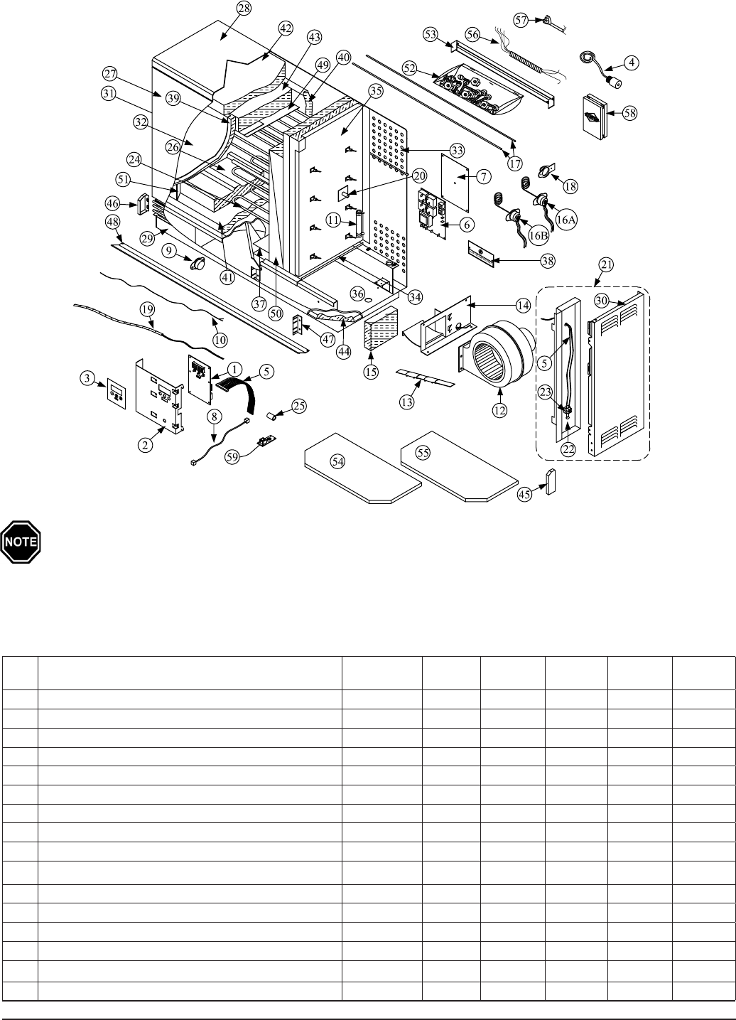
PARTS DIAGRAM
When ordering replacement parts, please include model number and serial number of the heater.
Ref
No.
Description
2102 Plug-in
Item #
2102
Item #
2103
Item #
2104
Item #
2105
Item #
2106
Item #
1. Processor Control Board 1023065R 1023065R 1023065R 1023065R 1023065R 1023065R
2. Processor Control Board Mounting Bracket 5943412 5943412 5943412 5943412 5943412 5943412
3. Faceplate Label 1159029 1159029 1159029 1159029 1159029 1159029
4. Outdoor Temperature Senor (optional) 1302033 1302033 1302033 1302033 1302033 1302033
5. Wiring Harness, Low Voltage 1011647 1011647 1011647 1011647 1011647 1011647
6. Base I/O Relay Board 1023078R 1023078R 1023078R 1023078R 1023078R 1023078R
7. Line Voltage Base I/O Barrier 1159060 1159060 1159060 1159060 1159060 1159060
8. Interface Cable, 18" 1010014R 1010014R 1010014R 1010014R 1010014R 1010014R
9. **Discharge Air High Limit Switch (285 Degree) Auto 1012018R 1012018R 1012018R 1012018R 1012018R 1012018R
" **Discharge Air High Limit Switch (285 Degree) Manual
1012080R 1012080R 1012080R 1012080R 1012080R 1012080R
10. Output Sensor (Thermocouple) 1040822 1040822 1040826 1040832 1040826 1040832
11. ***Blower Resistor (P-TECH) 1017047 1017049 1017049 1017049 1017049 1017049
" ***Blower Resistor (FASCO) 1017011 1017050 1017050 1017050 1017050 1017050
12. ***Blower Assembly (P-TECH) 1021036R 1021035R 1021035R 1021035R 1021035R 1021035R
***Blower Assembly (FASCO)
1021030R 1021032R 1021032R 1021032R 1021032R 1021032R
13. Damper Actuator Assembly 1043107R 1043106R 1043106R 1043106R 1043106R 1043106R
PARTS LIST
The blower resistor (Item #11) will vary depending on the blower (Item #12) installed in the heater.
Reference the Parts List for more details.
1.
2.

PARTS LIST CONTINUED
2100 Series Appendix A.03
*1012090R is a direct replacement in Model 2104.
**Manual and auto reset limits are not interchangeable. Verify serial number and/or style of limit switch before ordering.
***Optional voltages or wattages are available. Contact factory with model number and serial number of the heater.
Ref No. Description
2102 Plug-
in Item #
2102
Item #
2103
Item #
2104
Item #
2105
Item #
2106
Item #
14. Damper Assembly N/A N/A N/A N/A N/A N/A
15. Damper Assembly Insulation N/A N/A N/A N/A N/A N/A
16A. **Core Changing Limit Switch Auto (Back Panel) 1040816R 1040816R 1040816R 1040817R 1040817R 1040818R
16A. **Core Changing Limit Switch Manual (Back Panel) 1012088R 1012088R 1012088R 1012088R 1012090R 1012090R
16B. Clearance Violation Limit Switch Manual (Top Panel) 1012091R 1012091R 1012091R 1012091R 1012092R 1012092R
17. Core Changing High Limit Guide Tube (cut to size) 1105003 1105003 1105003 1105003 1105003 1105003
18. Core Changing High Limit Bracket 5940190 5940190 5940190 5940190 5940190 5940190
19. Brick Core Sensor (Thermocouple) 1043102R 1043102R 1043103R 1043103R 1043104R 1043104R
20. Brick Core Sensor Tube 5943222 5943222 5943220 5943220 5943220 5943220
21. Room Temperature Sensor Mounting Panel 1040860 1040860 1040860 1040860 1040860 1040860
22. Room Temperature Sensor 1013034 1013034 1013034 1013034 1013034 1013034
23. Terminal Block, Room Temperature Sensor 2- position 1016018 1016018 1016018 1016018 1016018 1016018
24. ***Heating Elements Contact factory with serial number of heater
25. High Temperature Vinyl 1015028 1015028 1015028 1015028 1015028 1015028
26. Heat Storage Brick 5903010 5903010 5903010 5903010 5903010 5903010
27. Painting Panel, Front 5943470 5943470 5943472 5943474 5943476 5943478
28. Painted Panel, Top (DO NOT REMOVE) 5943050 5943050 5943052 5943054 5943056 5943058
29. Painting Panel, Bottom 5943060 5943060 5943062 5943064 5943066 5943068
30. Painted Panel, Right 5943420 5943420 5943420 5943420 5943420 5943420
31. Painted Panel, Left 5943416 5943416 5943416 5943416 5943416 5943416
32. Galvanized Panel, Front 5943010 5943010 5943012 5943014 5943016 5943018
33. Galvanized Panel, Back 5943440 5943440 5943442 5943444 5943446 5943448
34. Galvanized Plate, Bottom 5943430 5943430 5943432 5943434 5943436 5943438
35. Galvanized Plate, Right 5943424 5943424 5943424 5943424 5943424 5943424
36. Galvanized Base Tray 5943450 5943450 5943452 5943454 5943456 5943458
37. Base Cap for Insulation 5943130 5943130 5943130 5943130 5943130 5943130
38. Low Voltage Raceway Cover 5943216 5943216 5943216 5943216 5943216 5943216
39. Insulation Panel, Front 1053010 1053010 1053012 1053014 1053016 1053018
40. Insulation Panel, Back 1053010 1053010 1053012 1053014 1053016 1053018
41. Insulation Panel, Bottom 1053020 1053020 1053022 1053024 1053026 1053028
42. 1 1/2" Blanket Insulation, Outer 1050005 1050005 1050005 1050005 1050005 1050005
43. 1 1/2" Blanket Insulation, Inner 1050004 1050004 1050004 1050004 1050004 1050004
44. 1" Blanket Insulation, Base 1050066 1050066 1050067 1050068 1050069 1050070
45. Grill End Bracket, Right
5943426 (includes one right and one left grill end bracket)
46. Grill End Bracket, Left
47 Grill Support Rail 5943024 5943024 5943024 5943024 5943024 5943024
48. Grill Slats 5943480 5943480 5943482 5943484 5943486 5943488
49. Aluminized Air Channel, Top Back 5949060 5949060 5949062 5949064 5949066 5949068
50. Aluminized Air Channel, Right 5943464 5943464 5943464 5943464 5943464 5943464
51. Aluminized Air Channel, Left 5949028 5949028 5949028 5949028 5949028 5949028
52. Mounting Hardware Package 1190038 1190032 1190032 1190032 1190032 1190032
53. Wall Support Bracket N/A 5943490 5943492 5943494 5943496 5943498
54. Security Base Shell 5942114 N/A N/A N/A N/A N/A
55. Security Base Filler 1190023 N/A N/A N/A N/A N/A
56. Wiring Harness (umbilical cord) Conduit N/A 1040800 1040800 1040800 1040800 1040800
57. Cord Assembly, Plug-in 1015000 N/A N/A N/A N/A N/A
58. Remote Room Temperature Senor (optional) 1302024 1302024 1302024 1302024 1302024 1302024
59. Time Clock Module (optional) 1301014 1301014 1301014 1301014 1301014 1301014
Appendix A.04 2100 Series
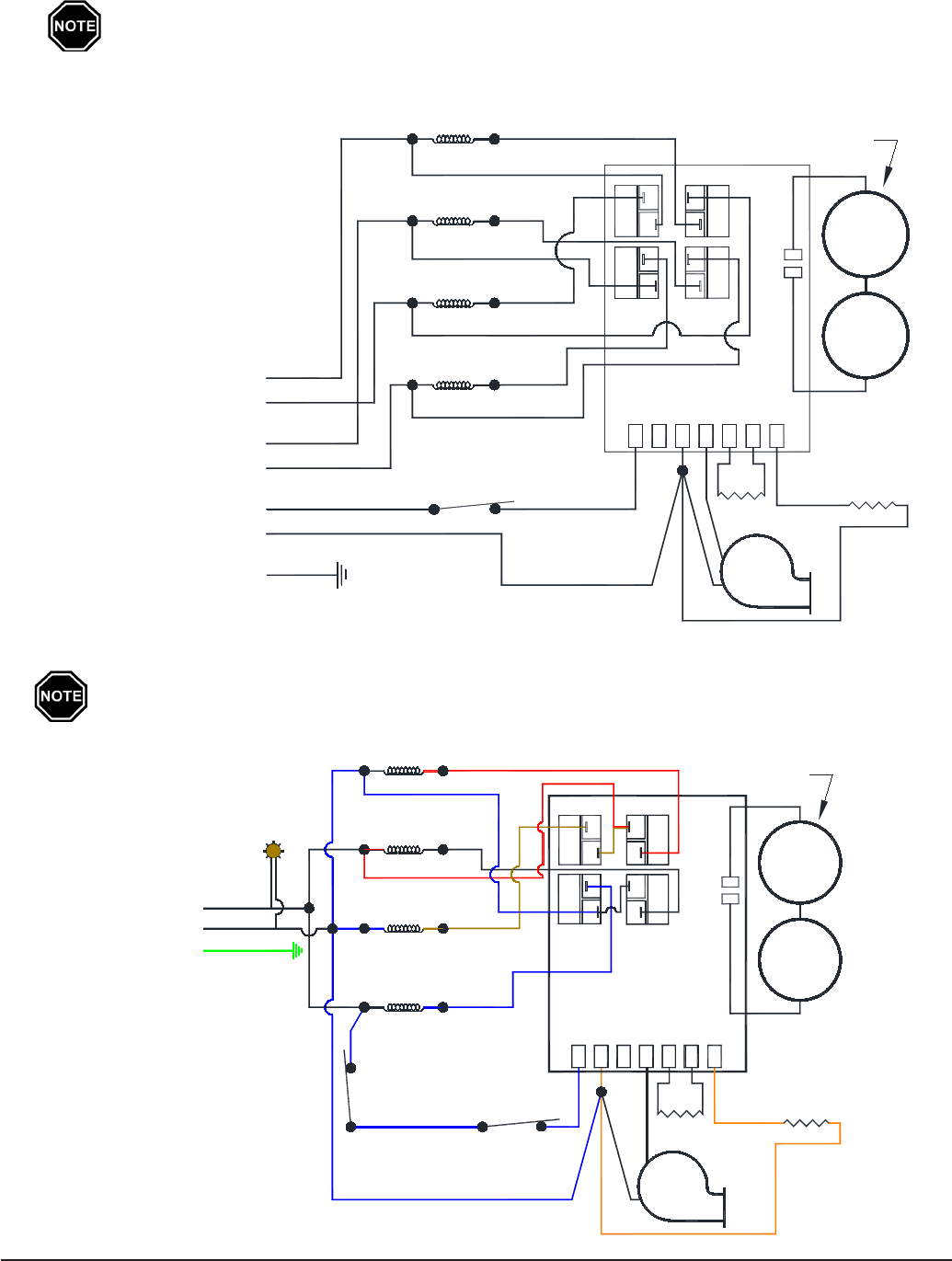
Models 2102, 2103, 2104 , 2105, and 2106
Connections shown are for systems with a 208/240V blower. If utilizing a 115V
blower and controls circuit, the blue/black (L1) connection must be the unground-
ed (hot) conductor of the power feed. Refer to the Unit Identication Label on the
lower left side panel for proper blower and heating element voltages.
Model 2102 (plug-in heater)
Connections shown are for systems with a 115V blower. Refer to the Unit Identica-
tion Label on the lower left side panel for proper blower and heating element volt-
ages.
INTERNAL LINE VOLTAGE WIRING DIAGRAMS
Black
Yellow
Blue
Blue
Blower Circuit
Green
Red
Black
Black
Blue/Black
Black
Charge Circuit #2
Heater Controls and
Limit
Temperature
Output
Red
Charge Circuit #1
Element #1
Element #2
Red
Element #3
Blue
Yellow
Element #4
Blower
Orange
Relay #1
Relay #3
Limit
Base I/O PCB
Resistor
L1
Resistor120 240 Blower
Control
Resistor
Orange
Damper
Damper
Relay #4
Relay #2
Charging
Clearance
Violation
Limit
Red
If Equipped from Factory
SWITCH
Element #1
Element #2
Element #3
Element #4
Blue/Black
Blue
Power
Cord
Black
TIP
Green
White
Blower
Orange
Relay #1
Relay #3
Base I/O PCB
Resistor
Resistor
Output
Temperature
Limit
120
L1
Blower240
Damper
Control
Resistor
Orange
Damper
Blue
Yellow
Charging
Limit
If Equipped from Factory
Black
Relay #2
Relay #4
Clearance
Violation
Limit
Red
Power
Indicator
Light

MANUAL RESET LIMIT CONTROLS
2100 Series Appendix A.05
INTERNAL LOW VOLTAGE WIRING DIAGRAM
Clearance Violation Limit:Locatedinsidetheheaterintheupperfront
corneroftheelectricalcompartment.Activationofthiscontrolwouldbe
indicatedbythedisplayscrolling“core”“fail”andwouldindicatethattheheater
has malfunctioned. Contact service technician to troubleshoot and repair the
root cause of the condition.
Discharge Air High Limit: The discharge air high limit is located in the lower
leftportionofthegrillareaandcanbeaccessedthroughthegrill.Activationof
this control would be indicated by a blank display screen. This control can be reset
by pressing the button on the limit control located just inside of the discharge air
grills.Ifthiscontrolactivatesmultipletimes,contactaqualiedservicetechnician
for repairs.
The discharge air high limit, the core charging high limit, and the clearance
violation limit switches are all manual reset limit controls installed for safety
purposes.Ifoneoftheselimitcontrolsopens,itmustbemanuallyresetbefore
operating the heater. To reset the limit controls, press and release the reset
button located in the middle of the control.
Risk of electric shock. Do not disassemble the
heater. There are no user serviceable parts inside.
WARNING
Gray
Gray
Purple
Purple
Blue
Yellow
Blue/White
M
Black
Green
Red
Red
Yellow
Yellow
-
+
+
-
A
P
M
M
Outdoor Sensor
Built-in or Remote Mount
Automatic Charge Control
Room Sensor
Outdoor Sensor
Room Sensor
Anticipated Peak Control (Specialty Applications)
Low Voltage Common (Grounded)
Room Temperature Set Back
Brick Core Sensor (Thermocouple)
Output Sensor (Thermocouple)
Peak Control
Low Voltage Hot
Core Charging High Limit: Locatedinsidetheheateratthebackof
theelectricalcompartment.Activationofthiscontrolwouldbeindicated
bythedisplayscrolling“core”“fail”andwouldindicatethattheheaterhas
malfunctioned.Iftheheaterisequippedwitha1/8”limitresetholeintherear,
upperlocationintheheater’ssidepanel,thislimitcanbereset.Iftheheateris
not equipped with this remote reset feature or if there has been multiple trip
conditions, contact service technician to troubleshoot and repair the root cause
of the condition.
Appendix A.06 2100 Series
HELP MENU
The 2100 series room heating unit contains a Help Menu which may be accessed by pressing and
releasing the Mbuttonuntil"HELP"isdisplayedonthefaceplate.Scrollthroughthemenuby
pressing either the up or the down arrow button.
Display
Reading Description
Fxxx FirmwareVersionNumber-Indicatestheversionofsoftwareinstalled.
Oxx OutdoorTemperature-Indicatescurrentoutdoortemperatureasrecognizedbythe
heater.
tL:xx TargetLevel-Indicatesthepercentageofbrickcorechargetheheatertargetsduring
ano-peakperiod.
CL:xx ChargeLevel-Indicatesthepercentageofheatstoragecurrentlyinthebrickcore.
HEx HeatingElementsActive-Indicatesthenumberofheatingelementscurrently
energized.
PCx PowerLineCarrierChannel-Indicatesthechannelonwhichtheheaterissetto
receivePLCcommunicationsignal.
Px PowerLineCarrierNetHitRatePercentage-Indicatesthepercentageof"GOOD"
communicationpacketsreceivedbytheheaterfromthePLCtransmittersystem.
PSx IndicateswhichSpecialtyTimerthesystemiscurrentlyusing.Thevaluedisplayed
will be zero if the Specialty Timer is not being utilized.
CC_x ChargeModeOperation-Indicatesthechargecontrolmethodbeingutilizedduring
o-peakperiods.
CA_x A-PeakModeOperation-Indicatesthechargecontrolmethodbeingutilizedduring
anticipated peak periods.
C1_x SpecialtyTimer#1ChargeMode-SpecialtyApplicationsOnly.
C2_x SpecialtyTimer#2ChargeMode-SpecialtyApplicationsOnly.
HUxx HeatUsage-Indicatestheamountofinputbeingdissipatedbythesystem.
A_xx TargetDischargeAirTemperature-Indicatesthedischargeairtemperaturethatthe
system is targeting.
cxxx CompressorOutputRelayDelayTimer-Indicatestimeremainingbeforeheatpump
compressorisenergized."cON"indicatestheheatpumpisenergized.
ERROR CODES
2100Seriesheatershaveanon-boarddiagnosticsystemtomonitorvariousoperatingconditions.If
operating conditions move outside the normal operating range,
anerrorcodewillbedisplayedonthefaceplate.Ifthereare
multiple errors simultaneously, only the highest priority error
code will be displayed. Once corrected, the next highest priority
codewillbedisplayed.Errorcodeswillbedisplayedonthe
faceplateas“Er—”(i.e.Er05).
Error Code Description
01 Core temperature sensor reading is out of normal
range.Anopen,shorted,orotherwisedefective
sensor or a circuit board which is out of calibration
could cause this.
02 Contactaqualiedservicetechnician.
HAZARDOUS VOLTAGE:
Risk of electric shock. Can
cause injury or death. Heater
may be connected to more
than one branch circuit.
Disconnect power to all
circuits before servicing.
DO NOT remove the painted
front panel while energized.
Equipment must be serviced
by a qualied technician.
WARNING

Error Code Description
03 Roomthermistortemperatureisoutofnormalrange.Thismayindicateanopen
thermistor, a short in the wiring, or a circuit board which is out of calibration.
04 Dischargeairtemperatureisoutofnormalrange.Ensureproperoperationofthe
dampersystem.Also,anopen,shorted,orotherwisedefectiveoutputsensorora
circuit board which is out of calibration could cause this.
05 Outdoor sensor (direct wired) temperature reading is out of normal range. The
thermistor circuit may be open or shorted, the processor control board may be out of
calibration,ortheremaybeanincorrectvalueinL035.
06 Outdoorsensortemperaturefromthetransmittingdevice(PLCsystem)isoutof
normal range. Check the outdoor sensor attached to the transmitting device and the
transmitter for proper operation.
07 Processorcontrolboardtemperaturesensorisoutofnormaloperatingrange.Verify
that none of the clearances have been violated and inspect the condition of the
processor control board.
08 Currently not utilized.
09 Currently not utilized.
10 Discharge air temperature has exceeded maximum operating temperature.
20 ThereisnocommunicationoccurringbetweentheBaseI/Oboardandtheprocessor
control board. This may be caused by a defective board interface cable or an
unresponsiveBaseI/Oboard.
21 Contactaqualiedservicetechnician.
22 Contactaqualiedservicetechnician.
23 ThereisnocommunicationoccurringwiththeSteesTimeClockModule.
24 Temperaturesensoroset/referenceisoutofrangeandindicatesthatoneofthe
sensors may be shorted to ground or the processor control board may be out of
calibration.
25 Contactaqualiedservicetechnician.
26 InsucientMainControlBoardMemory.Contactaqualiedservicetechnician.
27 InsucientPermanentMemory.Contactaqualiedservicetechnician.
28 Permanentmemorychangehasbeenmade.PresstheM buttontoaccept.Asthis
error message indicates a change has been made to the software program, it is
important to verify that all location settings are correct for the application.
29 On-boardcommunicationsystemisnotfullyoperable.Contactaqualiedservice
technician.
30 BaseI/Ocircuitboardisintestmode.Checkthejumpercongurationonthecircuit
board.
31 Contactaqualiedservicetechnician.
39 IndicatesthevalueinConguration2(C002)hasbeensettoavaluegreaterthanthe
valueinConguration1(C001).ThesystemwillnotchargeuntilthevalueinC002is
set lower than C001.
40 PressandreleasetheMbuttontocleartheerror.Iftheerrorcodereappears,contact
aqualiedservicetechnician.
41-44 Contactaqualiedservicetechnician.
Cold Core The temperature of the brick core has dropped below 40 degrees or the brick core
sensor may be open. Verify that the brick core sensor wiring is connected properly.
CoreFail Corechargingand/orclearanceviolationhighlimitswitchmaybeopen.
PLCFail Thesystemisconguredforpowerlinecarrier;however,isnotreceivingavalid
power line carrier communication signal.
2100 Series Appendix A.07
Appendix A.08 2100 Series
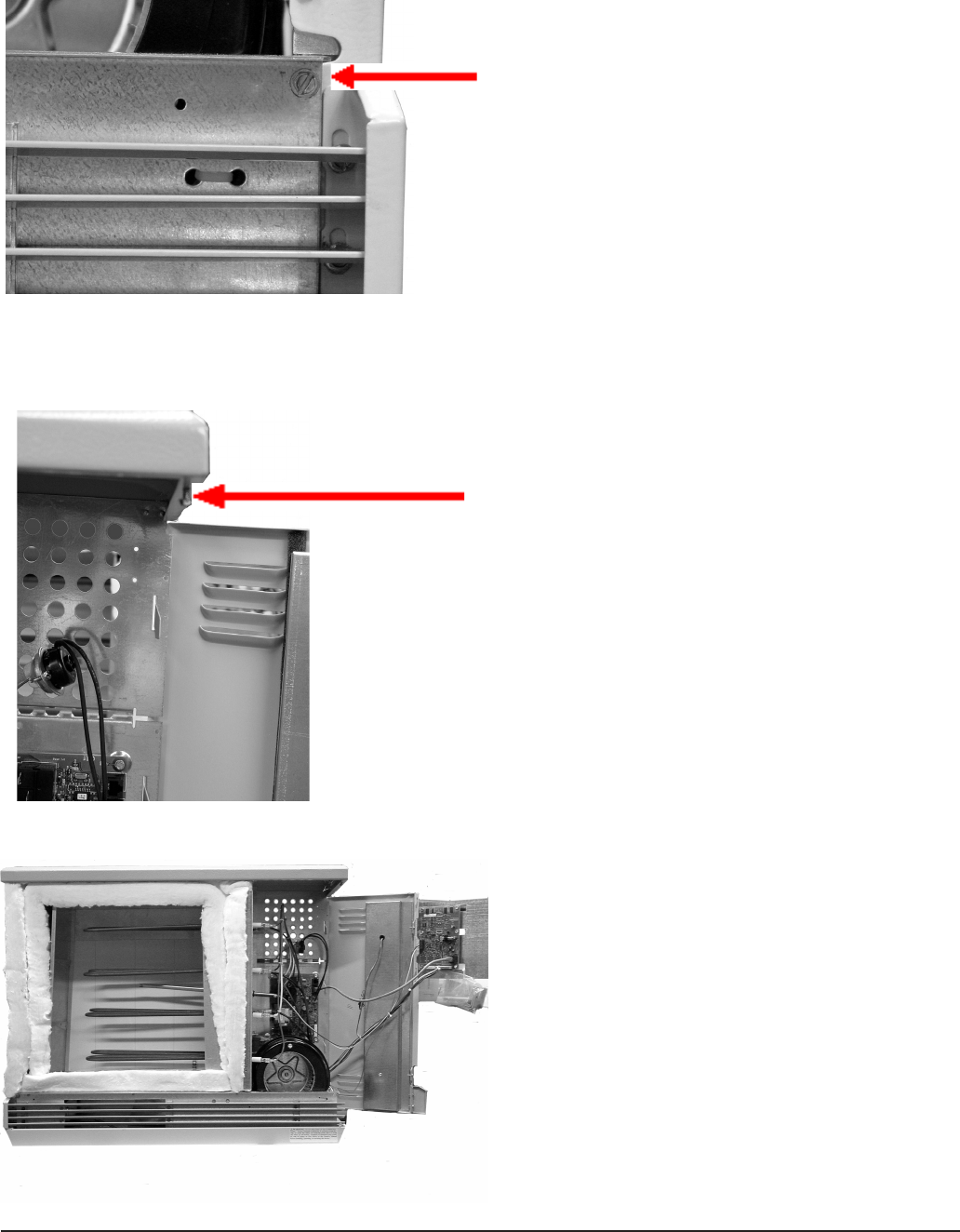
HINGING THE RIGHT SIDE PANEL
Foreaseinservicing,therightsidepanelofthe2100Seriesroomheatingunithingesopen.Fol-
low the instructions below to hinge the right side panel:
1. Withthepaintedfrontpanelo,remove
the screw located above the grill slats on
the lower right side of the heater.
2. Loosenthescrewlocatedatthetopright
corner of the electrical compartment.
3. Pushoutontherightsidepanel.

Anticipated Peak ~ Usedonlybycertain
power companies as an alternative method
ofstoringheatinthebrickcore.Indicatedby
an"A"onthesystemdisplay.Alsoreferred
toas"Pre-Peak".
Automatic Charge Control ~ Method
of brick core charge regulation where a
sensor monitors outdoor temperature
to automatically adjust the brick core
temperature.
Brick Core Charge Level ~ The amount of
heat currently stored in the brick core of the
heater.
Charge Period ~ O-peaktimeinwhich
the system is allowed to store heat in its
brickcore.Indicatedbya"C"onthesystem
display.
Control Panel~ Contains the buttons to
adjust and the display to indicate heater
functions.Locatedonthefrontoftheheater
in the upper right corner.
Control Period ~ On-peaktimeinwhich
the system is not allowed to store heat in its
brickcore.Indicatedbya"P"onthesystem
display.
Edit Mode ~ Processofchangingorviewing
the values in a microprocessor location.
This is accomplished with the use of the M
(mode) button, the (up arrow) button, and
the (down arrow) button.
Location (Function) ~ Wherethespecic
operating information of the heater is
stored. These locations are part of the
heater's microprocessor and are accessed
through the heater's control panel.
Displayedasan"L"onthefaceplatewhenin
the edit mode.
Location Value ~ Thespecicinformation
set and stored in a location on the heater's
microprocessorwhichdenesheater
operation.Avalueforaspeciclocationis
accessed through the heater's control panel.
Manual Charge Control ~ Method of
brick core charge regulation where the
owner must periodically adjust the brick
core temperature setting in relation to the
outdoor temperature.
Microprocessor ~ Device on the circuit
board of the heater which stores and
processes the information for controlling the
operation of the heater.
O-peak ~ The time during the day or
night when the power company can supply
electricity more economically and may
oeraspecialincentivesuchasareduced
electric rate or billing credits for the electricity
consumed during this time. Typically, electrical
usageisnotcontrolledduringano-peak
time. (The heater will provide heat to satisfy
comfort requirements during this time as well
as charge or store heat in its brick core.)
On-peak ~ The time during the day or night
when the power company experiences
a high demand for electricity. To limit
demand, certain appliances are controlled
to avoid usage by them and/or a premium
for the electricity consumed during this time
may be charged to discourage electrical
usage. (The heater is not allowed to charge
or store heat in its brick core during peak
periods.Heatingrequirementsaresatised
by the heat stored in its brick core during the
previouso-peakperiod.)
Outdoor Sensor ~ Device that senses
outdoor air temperature and communicates
this information to the heater.
Pre-Peak ~ Usedonlybycertainpower
companies as an alternative method of
storingheatinheater'sbrickcore.Also
referredtoas"AnticipatedPeak".
Room Temperature Set Point ~ The desired
room temperature the heater is to maintain
assetbytheowner.Iftheroomthermostat
senses a temperature below this point, the
heater's blower will come on and extract
heat from the brick core.
GLOSSARY
2100 Series Appendix A.09

DOCUMENT #1200340 REV 21
Registeringyourpurchaseisanessentialsteptoensurewarrantycoverage.AWarrantyRegistration
card is included with the Owner's Manual. Simply complete, detach the bottom portion, and return
thecardtoday.Retainthetopportionofthecardforyourles.
Warranty
Thank you for purchasing Steffes ETS heating equipment. We welcome your comments
relating to the heater and this manual. Enjoy your new purchase!
3050Hwy22North•Dickinson,ND58601-9413•www.stees.com
W
WARRANTY STATEMENT
Steeswarrantsforaperiodofve(5)yearsfollowingdelivery,limitedtoseven(7)yearsfromdate
ofmanufacture,ofanygoodsprovidedunderthisAgreementthatthegoodspurchasedhereunder
will be of merchantable quality, free from defects in material and workmanship, and that the goods
providedwillbenewandconformtothemechanicalandperformancespecicationsreferencedinany
drawingsprovidedbyStees.CustomershallpromptlyprovidenoticetoSteesofanygoodswhich
do not comply with such warranty.
THEWARRANTIES SET FORTHHEREIN ARE STEFFES’SOLE AND EXCLUSIVEWARRANTIES, AND THEY
AREMADEINLIEUOFALLOTHERWARRANTIES.THEREARENOOTHERWARRANTIES,EXPRESSOR
IMPLIED,WHETHERARISINGBYOPERATIONOFLAW,STATUTE,USAGEOFTRADE,CUSTOM,COURSE
OF DEALING OR PERFORMANCE, THE PARTIES’ CONDUCT OR OTHERWISE, FOR ANY PRODUCTS,
SERVICESOROTHERITEMSSOLDORFURNISHEDBYSTEFFES.WITHOUTLIMITINGTHEGENERALITY
OFTHE FOREGOING,ANDEXCEPTTOTHEEXTENTEXPRESSLY STATEDHEREIN,STEFFESDISCLAIMS
ALL IMPLIED WARRANTIESOF MERCHANTABILITYAND FITNESS FOR APARTICULAR PURPOSEAND,
EXCEPT TO THE EXTENT EXPRESSLY STATED HEREIN, THERE ARE NO WARRANTIES WHICH EXTEND
BEYONDTHEDESCRIPTIONONTHEFACEOFTHISDOCUMENT.STEFFESSHALLNOTBELIABLEFORANY
LOSSES,CLAIMS,DAMAGESORLIABILITYRELATINGTOLOSTPROFITSOROTHERCONSEQUENTIAL,
INCIDENTAL,EXEMPLARY,PUNITIVEORINDIRECTDAMAGESINCONNECTIONWITHORRELATINGTO
GOODSPROVIDEDHEREUNDER.
If the goods fail to meet the warranty requirements set forth herein, as mutually agreed by both
Parties,excludinggoodswhichhavebeensubjecttomisuse,abuse,negligence,accident,improper
maintenance or improper operations, Stees shall: repair or replace the product or part(s) only
which prove to be defective under normal use. The Customer shall be responsible for any labor costs
associated with the repair or replacement of the product or part(s), including the cost of returning the
defectiveproductorpart(s)toStees.
This Warranty is void if the product is moved from the premises in which it was originally installed. This
Warranty shall not apply to any product or part which has been altered in any respect, or improperly
installed, serviced or used, or has been subject to accident, negligence, abuse or misuse.
TheCustomerassumesallriskandliabilitywhatsoeverresultingfromtheuseofthisdevice.Inno
eventshallSteesbeliableforanyindirect,specialorconsequentialdamagesorlostprots.
This Limited Warranty contains the complete and exclusive statement of Stees’ obligations with
respecttothisdeviceandanypartsthereof.Theprovisionshereofmaynotbemodiedinanyrespect
exceptinwritingsignedbyadulyauthorizedocerofStees.
